USER GUIDE & INSTALLATION INSTRUCTIONS Classic 90 Gas Australia U110808-01A
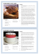
SLOW BAKED LEG OF LAMB METHOD INGREDIENTS • 2-3 large sprigs of rosemary • 4 large garlic cloves cut in half lengthways • 1.8 kg leg of lamb • 8 good quality anchovy fillets, halved • 100 ml olive oil • 250 ml dry red wine • Maldon salt and freshly ground black pepper 1. reheat the oven to 220 °C (for a conventional oven), 200 °C (for a P fan oven) or gas mark 7. 2. Pull the small sprigs off the rosemary branches and set aside with the garlic. 3.
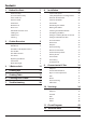
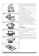
Contents 1. Before You Start... 1 8.
ii
1. Before You Start... • DO NOT use a steam cleaner on your cooker. Your cooker should give you many years of trouble-free cooking if installed and operated correctly. It is important that you read this section before you start. • Always keep combustible materials, e.g. curtains, and flammable liquids a safe distance away from the cooker. Personal Safety • DO NOT spray aerosols in the vicinity of the cooker while it is on. This appliance is for cooking purposes only.
Peculiar Smells Maintenance • Only a qualified service engineer should service the appliance and only approved spare parts should be used. It is recommended that this appliance is serviced annually. When you first use your cooker it may give off an odour. This should stop after use. Before using for the first time, make sure that all packing materials have been removed and then, to dispel manufacturing odours, turn the ovens to 200 °C and run for at least an hour.
a flaming pan on a surface unit by covering the pan completely with a well fitting lid or baking tray. If available, use a multi-purpose dry chemical or foamtype fire extinguisher. Fig. 1.1 • DO NOT modify this appliance. This appliance is not intended to be operated by means of external timer or separated remote-control system. ArtNo.324-0001 Steam burst • If flammable materials are stored in the drawer, oven(s) or grill(s) it may explode and result in fire or property damage.
Grill/Glide-out Grill™ Care Cleaning • When using the grill, make sure that the grill pan is in position and pushed fully in, otherwise the control knobs may become very hot. • Isolate the electricity supply before carrying out any thorough cleaning. Allow the cooker to cool. • In the interests of hygiene and safety, the cooker should be kept clean at all times as a build up in fats and other food stuff could result in a fire.
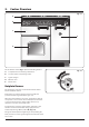
2. Cooker Overview DocNo.020-0006 - Overview - 90DF - Prof+ Fig. 2.1 A B H M G C E D The 90 dual fuel cooker (Fig. 2.1) has the following features: A. 5 hotplate burners including a wok burner B. A control panel incorporating a timer C. A glide-out grill D. Main fan oven E. Tall fan oven Fig. 2.2 Hotplate Burners The drawing by each of the central knobs indicates which burner that knob controls.
If, when you let go of the control knob, the burner goes out, then the FSD has not been bypassed. Turn the control knob to the OFF position and wait for one minute before you try again, this time making sure to hold in the control knob for slightly longer. Fig. 2.3 Adjust the flame height to suit by turning the knob counterclockwise (Fig. 2.3). If a burner flame goes out, turn off the control knob and leave it for one minute before relighting it. Make sure that the flames are under the pans.
The Wok Cradle (optional extra) Fig. 2.9 The wok cradle is designed to fit a 35 cm wok. If you use a different wok, make sure that it fits the cradle. Woks vary very widely in size and shape. It is important that the wok sits down on the pan support – however, if it is too small, the cradle will not support it properly (Fig. 2.9). The cradle should be used on the wok burner only.
The Glide-out Grill Fig. 2.15 CAUTION: Accessible parts may be hot when the grill nn is in use. Young children should be kept away. Open the door and pull the grill pan carriage forward using the handle (Fig. 2.15). The burner does not glow red when in use; food cooks from the heat of the flame. The first time you light the grill there may be a little smoke given off – this is perfectly normal. ArtNo.331-0001Grill pan pulled forwards Operation Fig. 2.
The Ovens ArtNo.323-0003 Bray gas oven burner flame The clock must be set to the time of day before the ovens will work. See the following section on ‘The Clock’ for instructions on setting the time of day. Fig. 2.19 References to ‘left-hand’ and ‘right-hand’ ovens apply as viewed from the front of the appliance. The left-hand oven is a programmable gas oven and the right-hand oven is a tall fan oven.
Meat Beef Rare 60 °C / 140 °F Medium 71 °C / 160 °F Well done 77 °C / 170 °F Lamb Pork Should further browning be necessary, uncover the meat and increase the temperature to gas mark 4 for a short period. Temperature Cut root vegetables into small pieces unless cooking whole, e.g. jacket potatoes. Cover dishes tightly with a lid or foil to prevent evaporation and transfer of flavour.
Accessories Fig. 2.27 Oven Shelves – Left-hand (Main) Oven Shelf guard The cooker is supplied with 2 flat shelves (Fig. 2.27). The oven shelves can be easily removed and refitted. Pull the shelf forward until the back of the shelf is stopped by the shelf stop bumps in the oven sides (Fig. 2.28). Front Lift up the front of the shelf so the back of the shelf will pass under the shelf stop and then pull the shelf forward (Fig. 2.29). Fig. 2.
3. 3 Button clock Using the clock Fig. 3.1 You can use the clock to turn the programmable oven on and off. The clock must be set to the time of day before the oven will work. NOTE: When using the timer functions, first set the clock as required before setting the oven temperature. ArtNo.306-0001 - 3-button clock The oven can be switched on when the cook symbol [ ] is displayed. Fig. 3.2 Setting the clock ArtNo.306-0001 - 3-button clock 1. The LCD clock is shown in (Fig. 3.1).
3. When the ‘stop time’ is reached an alarm will sound and the oven will stop working. The word ‘AUTO’ will flash on the display (Fig. 3.6). 4. Press any button to stop the alarm and return to manual cooking. If the alarm is not stopped, it will stop automatically after 7 minutes. Fig. 3.7 ArtNo.306-0001 - 3-button clock To start and then stop the programmable oven Set the programmable oven to automatically start and stop using a combination of the ‘cook period’ and ‘stop time’. Fig. 3.
4. Cooking tips Tips on cooking with the timer General oven tips If you want to cook more than one dish, choose dishes that require approximately the same cooking time. However, dishes can be ‘slowed down’ slightly by using small containers and covering them with aluminium foil, or ‘speeded up’ slightly by cooking smaller quantities or placing them in larger containers. The wire shelves should always be pushed firmly to the back of the oven.
5. Cooking Table The oven control settings and cooking times given in the table below are intended to be used as a guide only. Individual tastes may require the temperature to be altered to provide a preferred result. Food is cooked at lower temperature in a fan oven than in a conventional oven. When using recipes, reduce the fan oven temperature by 10 °C and the cooking time by 5-10 minutes. The temperature in the fanned oven does not vary with height in the oven so you can use any shelf.
6. Cleaning Your Cooker Essential Information Fig. 6.1 Isolate the electricity supply before carrying out any thorough cleaning. Allow the cooker to cool. A C NEVER use paint solvents, washing soda, caustic nn cleaners, biological powders, bleach, chlorine based B bleach cleaners, coarse abrasives or salt. DO NOT mix different cleaning products – they may nn react together with hazardous results.
Glide-out Grill Fig. 6.5 Before you remove any of the grill parts for cleaning make sure that they are cool, or use oven gloves. nn DO NOT use any abrasive substances. nn The face of the grill burner will darken with use – this is perfectly normal. Any fat or grease will burn off. Do not try to clean it – the small holes could get blocked and affect burner performance. ArtNo.331-0001Grill pan pulled forwards The grill pan and trivet (Fig. 6.
Fig. 6.11 Carefully lift off the outer door panel. The inside face of the glass panels can now be cleaned – take care not to disturb or wet the door insulation. Thermostat temperature sensor Note: If the door is triple glazed then the inner two panels are fixed together and should not be separated. After cleaning, carefully refit the outer door panel and replace the side fixing screws.
The Tall Oven To clean the oven sides, slide out the shelves, unhook the supports from the oven sides and lift out (Fig. 6.15). Cleaning Table Cleaners listed (Table 6.1) are available from supermarkets or electrical retailers as stated. For enamelled surfaces use a cleaner that is approved for use on vitreous enamel. Regular cleaning is recommended. For easier cleaning, wipe up any spillages immediately.
7. Troubleshooting Hotplate/Cooktop ignition or hotplate burners faulty Food is cooking too slowly, too quickly, or burning Is the power on? Is the clock illuminated? Cooking times may differ from your previous oven. If not, there maybe something wrong with the power supply. Check that you are using the recommended temperatures and shelf positions – see the oven cooking guide. The oven control settings and cooking times are intended to be used only as a guide.
Oven light is not working Fig. 7.1 The bulb has probably burnt out. You can buy a replacement bulb (which is not covered under the warranty) from a good electrical shop. Ask for a 15 W – 230 V lamp, FOR OVENS. It must be a special bulb, heat resistant to 300 °C (Fig. 7.1). ArtNo.324-0005 Oven light bulb Turn off the power at the circuit breaker. Before removing the existing bulb, turn off the power supply and make sure that the oven is cool. Open the oven door and remove the oven shelves. Fig. 7.
INSTALLATION Check the appliance is electrically safe and gas sound when you have finished. 8. Installation Service and Spares Firstly, please complete the appliance details below and keep them safe for future reference – this information will enable us to accurately identify the particular appliance and help us to help you. Filling this in now will save time and inconvenience if you later have a problem with the appliance. It may also be of benefit to keep your purchase receipt with this leaflet.
INSTALLATION Check the appliance is electrically safe and gas sound when you have finished. Safety Requirements and Regulations Provision of Ventilation This appliance is not connected to a combustion products evacuation device. Particular attention shall be given to the relevant requirements regarding ventilation in accordance with AS/NZS 5601. Please read the Before you start... chapter, before nn you begin any installation and maintenance work on this appliance.
INSTALLATION Check the appliance is electrically safe and gas sound when you have finished. You will need the following equipment to complete the cooker installation satisfactorily: Checking the Parts: • Flexible gas hose. 3 pan supports Plinth Griddle plate Grill pan & trivet • Gas pressure tester/manometer. • Multimeter: For electrical checks. You will also need the following tools: 1. Electric drill 2. Masonry drill bit (only required if fitting the cooker on a stone or concrete floor) 3.
INSTALLATION Check the appliance is electrically safe and gas sound when you have finished. Positioning the Cooker Fig. 8.1 The diagram (Fig. 8.1) shows the minimum recommended distance from the cooker to nearby surfaces as given in AS/NZS 5601. Where the appliance is installed next to cabinetry, the cabinet material must be capable of withstanding 70°C. If this appliance is installed near vinyl wrapped surfaces, use an installation kit available from the vinyl-wrap supplier.
INSTALLATION Check the appliance is electrically safe and gas sound when you have finished. Moving the Cooker Fig. 8.3 On no account try and move the cooker while it is nn plugged into the electricity supply. The cooker is very heavy, so take great care. nn We recommend that two people manoeuvre the cooker. Make sure that the floor covering is firmly fixed, or removed, to prevent it being disturbed when moving the cooker around. Fig. 8.
INSTALLATION Check the appliance is electrically safe and gas sound when you have finished. Fitting the Stability Bracket and Chain Fig. 8.6 A stability bracket and chain MUST be fitted when nn the cooker is connected to a flexible gas supply. Unless properly installed, the cooker could be tipped by leaning on the door. Injury might result from spilled hot liquids or from the cooker itself.
INSTALLATION Check the appliance is electrically safe and gas sound when you have finished. Fitting the Oven Burner Trim Fig. 8.10 The oven burner has an enamel burner trim. To fit the trim, simply hook it over the front of the oven burner bracket (Fig. 8.10). Make sure that the burner trim is central to the oven burner bracket. Oven burner bracket Gas Connection Must be in accordance with the relevant standards. The gas supply needs to terminate with a down-facing (Fig. 8.
INSTALLATION Check the appliance is electrically safe and gas sound when you have finished. Electrical Connection Earth Continuity Check WARNING: THIS COOKER MUST BE EARTHED. nn The cooker must be disconnected from the power supply. This appliance must be installed by a qualified electrician to comply with with current AS/NZS 3000 Wiring Rules and regulations in force. Using an multimeter or ohmmeter to check the resistance, test the leads from any of the cooker’s earth points (e.g.
INSTALLATION Check the appliance is electrically safe and gas sound when you have finished. Fixed Wiring Fig. 8.13 Disconnect from the mains supply. nn For connection to fixed wiring, i.e. flexible conduit, Remove the electrical terminal cover on the back panel (Fig. 8.13). Remove the M4 screw securing the reducer plates to the conduit box (Fig. 8.14). Fit the conduit box to the cooker using the two M5 screw fittings located at the top of the box and the M4 screw (Fig. 8.15).
INSTALLATION Check the appliance is electrically safe and gas sound when you have finished. Final Checks Fig. 8.18 Note: The clock must be set before the ovens will work. See ‘The Clock’ section for instructions on setting the time of day. Hotplate Check Check each burner in turn. There is a Flame Supervision Device (FSD) that stops the flow of gas to the burner if the flame goes out. For each burner, turn the control knob to the solid flame symbol. Press in the control knob.
WARNING – SERVICING TO BE CARRIED OUT ONLY BY AN AUTHORISED PERSON Disconnect from electricity and gas before servicing. Check appliance is safe when you have finished. 9. Conversion to LP Gas Conversion from Natural Gas (1.0 kPa) to LPG X Propane (2.54 kPa) Fig. 9.1 A suitably competent person must perform the nn conversion. After conversion the installation must B A comply with the relevant regulations and also the local electricity supply company requirements.
WARNING – SERVICING TO BE CARRIED OUT ONLY BY AN AUTHORISED PERSON Disconnect from electricity and gas before servicing. Check appliance is safe when you have finished. Grill Fig. 9.4 Injector Lift up the spring retaining the grill holder and slide the jet holder out of the burner venturi (Fig. 9.4). Remove the grill jet from the adaptor and fit a new jet; see the ‘Technical Data’ for the correct jets. Refit the jet holder back into the burner venturi. ArtNo.
WARNING – SERVICING TO BE CARRIED OUT ONLY BY AN AUTHORISED PERSON Disconnect from electricity before servicing. Check appliance is safe when you have finished. 10. Servicing BEFORE SERVICING ANY GAS CARRYING nn COMPONENTS TURN OFF THE GAS SUPPLY Fig. 10.1 Check the appliance is gas sound after completion nn of service. When checking for gas leaks DO NOT use washing up liquid – this can corrode. Use a product specifically manufactured for leak detection.
WARNING – SERVICING TO BE CARRIED OUT ONLY BY AN AUTHORISED PERSON Disconnect from electricity before servicing. Check appliance is safe when you have finished. 2.3 To Change a Hotplate Burner Injector Hotplate Remove the burner cap and head. Remove the old injector. 2.1 To Remove the Hotplate Fit the new injector. Reassemble in the reverse order. Check the appliance is gas sound. Pull the cooker forward to gain access to the rear. Left-hand tray 2.
WARNING – SERVICING TO BE CARRIED OUT ONLY BY AN AUTHORISED PERSON Disconnect from electricity before servicing. Check appliance is safe when you have finished. Controls 3.1. To Replace the Ignition or Light Switch DISCONNECT FROM THE ELECTRICITY SUPPLY. Remove the control panel (see 1.1). Note: The old switch may be destroyed during removal. Remove the old switch from its bezel by gripping the switch body behind the control panel and twisting sharply.
WARNING – SERVICING TO BE CARRIED OUT ONLY BY AN AUTHORISED PERSON Disconnect from electricity before servicing. Check appliance is safe when you have finished. Grill Spring clip BEFORE SERVICING ANY GAS CARRYING COMPONENTS, TURN OFF THE GAS SUPPLY. Fig. 10.4 4.1 To Change the Grill Control Tap Disconnect from the electricity supply. Remove the control panel (see 1.1). Lift up the right-hand hotplate tray front (see 2.1).
WARNING – SERVICING TO BE CARRIED OUT ONLY BY AN AUTHORISED PERSON Disconnect from electricity before servicing. Check appliance is safe when you have finished. Ovens Fig. 10.6 5.1 To Remove the Tall Oven Inner Back Open the tall oven door and remove the 2 screws and washers securing the inner back to the back of the oven. Carefully lift away the inner back. Reassemble in reverse order. Check the door for correct operation. 5.2 To Remove an Oven Thermostat Disconnect from the electricity supply. Fig.
WARNING – SERVICING TO BE CARRIED OUT ONLY BY AN AUTHORISED PERSON Disconnect from electricity before servicing. Check appliance is safe when you have finished. 5.5 To Change the Main Oven Burner Injector 5.10 To Remove the Tall Oven Element DISCONNECT FROM ELECTRICITY SUPPLY. Remove the main oven burner (see 5.3). The injector is now accessible. Remove the old jet and fit the new one. Remove the tall oven inner back (see 5.1). Reassemble in the reverse order.
WARNING – SERVICING TO BE CARRIED OUT ONLY BY AN AUTHORISED PERSON Disconnect from electricity before servicing. Check appliance is safe when you have finished. Fig. 10.9 Doors Fig. 10.10 6.1 To Remove the Grill Door Remove the left-hand side panel (see 1.2). Remove the plinth (4 screws) and the central vertical cover (5 screws). Remove the 2 countersunk screws (1 each side) securing the grill hinge arms to the front of the grill chamber. 2 1 ArtNo.320-0001 Door hinges Fig. 10.
WARNING – SERVICING TO BE CARRIED OUT ONLY BY AN AUTHORISED PERSON Disconnect from electricity before servicing. Check appliance is safe when you have finished. 6.7 To Remove the Tall Oven Door Fig. 10.16 Open the tall oven door. Supporting the door, remove the 2 screws securing the upper hinge and packing to the cooker front. Remove the door from the lower hinge by lifting slightly and moving outwards. Reassemble in reverse order. 6.
11. Circuit Diagram b C J v br 1 br br br or A1 y 1 2 y E P2 or br r D or br 1 r br B y br 2 N L b br b A2 r N 1a b y F v P1 br br or r I r b b r M or G b b or H K c y 1 b b b br br 2 3 5 b b 6 br b br Sensor E v L N A br JT2 Spark b 1 N JT1 A 4 b Con7 1 b Con6 b c ArtNo.080-0002 Classic 90 circuit diagram br Key Key br br b br b c b b The connections shown in the circuit diagram are for single-phase.
12. Technical Data This cooker is designed for use on Natural Gas, although a conversion for LP (LPG X Propane (2.54 kPa)) gas is packed with the cooker. INSTALLER: Please leave these instructions with the user. DATA BADGE LOCATION: Cooker back, serial number repeater badge below oven door opening. COUNTRY OF DESTINATION: Australia. Connections Gas (Rp ½ at rear right-hand side) Natural gas Propane Electric 1 kPa 2.75 kPa 230 V 50 Hz See the appliance badge for test pressures.
Clarence Street, Royal Leamington Spa, Warwickshire, CV31 2AD, England. Tel: +44 (0) 800 804 6261 | +44 (0) 370 789 5107 E-mail: consumers@falconappliances.co.