USER GUIDE & INSTALLATION INSTRUCTIONS Classic & Professional+ 90 Induction Australia U110695-02A
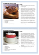
SLOW BAKED LEG OF LAMB METHOD 1. reheat the oven to 220 °C (for a conventional oven), 200 °C (for a P fan oven) or gas mark 7. 2. Pull the small sprigs off the rosemary branches and set aside with the garlic. 3. sing the tip of a paring knife, make up to 20 well-spaced cuts into U the flesh of the lamb, about 2.5 cm inch deep. Divide the rosemary sprigs, garlic and anchovies and push down into the cuts. Place the leg on a large roasting tin and pour over the oil, massaging it all over the joint.
Contents 1. 2. Before you start... 1 7. Cleaning your cooker 20 Personal safety 1 Electrical connection safety 1 8. Troubleshooting 24 Peculiar smells 2 9.
ii
1. Before you start... This User Guide covers a number of different models. Although some of the illustrations will look different to your particular model, the functions will be the same. • ALWAYS keep combustible materials, e.g. curtains, and flammable liquids a safe distance away from your cooker. • DO NOT spray aerosols in the vicinity of the cooker while it is on. Your cooker should give you many years of trouble-free cooking if installed and operated correctly.
Peculiar smells • DO NOT use unstable saucepans. ALWAYS make sure that you position the handles away from the edge of the hotplate. When you first use your cooker it may give off an odour. This should stop after use. Before using your cooker for the first time, make sure that all packing materials have been removed and then, to dispel manufacturing odours, turn all the ovens to 200°C and run for at least an hour. • NEVER leave the hotplate unattended at high heat settings.
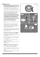
Induction care Fig. 1.1 • IMPORTANT INFORMATION FOR PACEMAKER AND IMPLANTED INSULIN PUMP USERS: The functions of this hob comply with the applicable European standards on electromagnetic interference. If you are fitted with a pacemaker or implanted insulin pump and are concerned please consult your doctor for medical advice. • When the hob is in use keep magnetic items away, such as credit and debit cards, floppy disk, calculators, etc.
• Take care NOT TO PLACE HOT LIDS onto the hob surface (Fig. 1.5). Lids that have been used to cover a hot pan can “stick” or create a “vacuum” effect to the Glass Hob. Should this occur, DO NOT attempt to lift the lid off the glass surface, this may damage the glass. Instead slide the lid to the edge of the hob surface and remove, taking care not to scratch the hob surface.
Cooker care • Make sure the shelves are pushed firmly to the back of the oven. DO NOT close the door against the oven shelves. As steam can condense to water droplets on the cool outer trim of the oven, it may be necessary during cooking to wipe away any moisture with a soft cloth. This will also help to prevent soiling and discolouration of the oven exterior by cooking vapours (Fig. 1.7). • DO NOT use aluminium foil to cover shelves, linings or the oven roof.
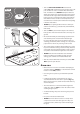
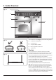
2. Cooker Overview Fig. 2.1 ArtNo.025-0005 - Overview - 90 induction - 2 button clock & GO grill A B C E D The 90 induction cooker (Fig. 2.1) has the following features: Fig. 2.2 A. 5 induction cooking zones B. A control panel C. A separate Glide-out Grill™ D. Main, programmable fan oven E. Tall fan oven The Hob Use only pans that are suitable for induction hobs. We recommend stainless steel, enamelled steel pans or cast iron pans with enamelled bases.
Make sure that the base of the pan is clean and dry to prevent any residue burning onto the hob panel. This also helps prevent scratches and deposits. Always use pans that are the same size as (or slightly larger than) the areas marked on the hob. Using a lid will help the contents boil more quickly. The induction hob comprises of five cooking zones containing induction elements with different ratings and diameters (Fig. 2.4) each with a pan detector and residual heat indicator, and a hob control display.
Power level Automatic heat-up time at 100% (min:sec) 1 0:48 2 2:24 3 3:50 4 5:12 5 6:48 6 2:00 7 2:48 8 3:36 When the Automatic Heat-up function is activated, the hob control display will flash alternately between the [A ] setting and the chosen power level. Once the Automatic Heat-up time has ended the hob display will stop flashing and will show the chosen power level.
Low Temperature Setting, L1/L2 Each cooking area is equipped with 2 low temperature settings: • • Maximum Operating Time Power Level This function should only be used when heating nn from cold L1 will maintain a temperature of about 40 °C – ideal for gently melting butter or chocolate. L2 will maintain a temperature of about 90 °C – ideal for simmering (bring the pan to the boil and then select L2 to keep soups, sauces, stews, etc at an optimal simmer).
The Glide-out Grill Fig. 2.9 CAUTION: This appliance is for cooking purposes nn only. It must not be used for other purposes, for example room heating. CAUTION: Accessible parts may be hot when the grill nn is in use. Young children should be kept away. Open the door and pull the grill pan carriage forward using the handle (Fig. 2.9 or Fig. 2.10 depending on model). ArtNo.
The Ovens Fig. 2.14 The clock must be set to the time of day before the ovens will work. See the following section on ‘The Clock’ for instructions on setting the time of day. References to ‘left-hand’ and ‘right-hand’ ovens apply as viewed from the front of the appliance. Both ovens are fan ovens. ArtNo.235-0004 Classic DL oven 1 Fan ovens circulate hot air continuously, which means faster, more even cooking.
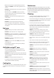
Accessories Fig. 2.17 Oven Shelves – Left-hand (Main) Oven Shelf guard The oven shelves (Fig. 2.17) are retained when pulled forward but can be easily removed and refitted. Pull the shelf forward until the back of the shelf is stopped by the shelf stop bumps in the oven sides (Fig. 2.18). Lift up the front of the shelf so the back of the shelf will pass under the shelf stop and then pull the shelf forward (Fig. 2.19). Front Fig. 2.
3. 2 Button - rotary clock The clock must be set to the time of day before the oven will work. Setting the Clock 1. Once the cooker is connected and switched on, the display will start to flash. 2. To set the time, turn the Timer (A) knob to the Clock (C) setting and back to the Manual (D) position. The centre dot will flash indicating the time can be set. Turn the Adjusting (B) knob either clockwise or counterclockwise (Fig. 3.1) to set the time. 3. C D A ArtNo.
To stop the oven at a specific time of day Fig. 3.5 You have set the required temperature and function mode and you would like the oven to automatically stop. TOP TIP G A Make a note of the current time so you do not forget. B 1. Turn the Timer (A) knob to the Stop Time (G) setting. ‘AUTO’ will show in the display (Fig. 3.5). 2. Turn the Adjusting (B) knob to the amount of cooking time required. The display will show the current time plus the additional cooking time you have set (Fig. 3.6). 3.
To start and stop the oven automatically Fig. 3.9 The timer allows you to automatically start and stop by a combination of the length of the cooking time and the stop time. Giving you the flexibility to cook casseroles etc while you are out. You cannot set the actual start time. 1. Turn the Timer (A) knob to the Cook Time (F) setting. Turn the Adjusting (B) knob clockwise to set the length of the cooking time required (Fig. 3.9). 2. Turn the Timer (A) knob to the Stop Time (G) setting (Fig. 3.10).
4. 3 Button clock Using the clock Fig. 4.1 You can use the clock to turn the programmable oven on and off. The clock must be set to the time of day before the oven will work. NOTE: When using the timer functions, first set the clock as required before setting the oven temperature. ArtNo.306-0001 - 3-button clock The oven can be switched on when the cook symbol [ ] is displayed. Fig. 4.2 Setting the clock 1. The LCD clock is shown in (Fig. 4.1).
Fig. 4.7 3. When the ‘stop time’ is reached an alarm will sound and the oven will stop working. The word ‘AUTO’ will flash on the display (Fig. 4.6). 4. Press any button to stop the alarm and return to manual cooking. If the alarm is not stopped, it will stop automatically after 7 minutes. ArtNo.306-0001 - 3-button clock To start and then stop the programmable oven Set the programmable oven to automatically start and stop using a combination of the ‘cook period’ and ‘stop time’. Fig. 4.
5. Cooking Tips Hints on Using Your Induction Cooker General Oven Tips If you have not used an induction cooker before please be aware of the following: The wire shelves should always be pushed firmly to the back of the oven. • Make sure that the pans you have or buy are suitable for use on the induction hob. Stainless steel, enamelled steel or cast iron is ideal. Double check before you buy pans – they must have bases that would attract a magnet.
6. Cooking Table The oven control settings and cooking times given in the table below are intended to be used as a guide only. Individual tastes may require the temperature to be altered to provide a preferred result. Food is cooked at lower temperature in a fan oven than in a conventional oven. When using recipes, reduce the fan oven temperature by 10 °C and the cooking time by 5-10 minutes. The temperature in the fan oven does not vary with height in the oven so you can use any shelf.
7. Cleaning your cooker DocNo.040-0004 - Cleaning - 110 ceramic GENERIC Isolate the electricity supply before carrying out any nn major cleaning. Then allow the cooker to cool. Fig. 7.1 NEVER use paint solvents, washing soda, caustic nn cleaners, biological powders, bleach, chlorine based bleach cleaners, coarse abrasives or salt. DO NOT mix different cleaning products – they may nn react together with hazardous results.
Grills Fig. 7.2 The grill pan and trivet should be washed in hot soapy water. After grilling meats or any foods that soil, leave to soak for a few minutes immediately after use. Stubborn particles may be removed from the trivet using a nylon brush. Alternatively, the grill pan can be washed in a dishwasher. Before you remove any of the grill parts for cleaning, nn make sure that they are cool, or use oven gloves. DO NOT use any abrasive substances. nn ArtNo.
Glass fronted door panels Fig. 7.7 The oven door front panels can be taken off so that the glass panels can be cleaned. Move the cooker forward to gain access to the sides (see the ‘Moving the Cooker’ section under ‘Installation’). Open the oven door slightly and remove the front panel fixing screws from the door sides, two each side (Fig. 7.7). Carefully lift off the outer door panel. The inside face of the glass panels can now be cleaned – take care not to disturb or wet the door insulation. ArtNo.
Cleaning table Cleaners listed (Table 7.1) are available from supermarkets or electrical retailers as stated. For enamelled surfaces use a cleaner that is approved for use on vitreous enamel. Regular cleaning is recommended. For easier cleaning, wipe up any spillages immediately. Hotplate Part Finish Recommended Cleaning Method Hob top Enamel or stainless steel Hot soapy water, soft cloth. Any stubborn stains remove gently with a nylon scourer.
8. Troubleshooting DocNo.050-0001 - Troubleshooting - Induction GENERIC Interference with and repairs to the hob MUST NOT nn be carried out by unqualified persons. Do not try The cooling fan The induction hob incorporates a cooling fan. This cooling fan is active when either the grill or the oven(s) are on. Under certain conditions, the cooling fan may remain active when the grill or oven(s) are switched off. This is normal and the fan will switch off automatically.
Food is cooking too slowly, too quickly, or burning Fig. 8.1 Cooking times may differ from your previous oven. Check that you are using the recommended temperatures and shelf positions – see the oven cooking guide. Then adjust the settings according to your own individual tastes. ArtNo.324-0005 Oven light bulb The oven light is not working The bulb has probably blown. You can buy a replacement bulb (which is not covered under the guarantee) from most electrical stores.
The timed oven is not coming on when turned on manually Is the power on? Is the clock illuminated? If not, there may be something wrong with the power supply.
INSTALLATION Check the appliance is electrically safe when you have finished. 9. Installation Service and Spares Firstly, please complete the appliance details below and keep them safe for future reference – this information will enable us to accurately identify the particular appliance and help us to help you. Filling this in now will save time and inconvenience if you later have a problem with the appliance. It may also be of benefit to keep your purchase receipt with this leaflet.
INSTALLATION Check the appliance is electrically safe and gas sound when you have finished. You will need the following equipment to complete the cooker installation satisfactorily: Multimeter (for electrical checks). You will also need the following tools: 1. Steel tape measure 2. Cross-head screwdriver 3. Flat-bladed screwdriver 4. Spirit level 5. Pencil 6. Adjustable spanner 7. 3 mm and 4 mm Allen keys 8.
INSTALLATION Check the appliance is electrically safe and gas sound when you have finished. Positioning the Cooker 9.1 ArtNo.090-0028 - 90 cooker min spacingFig. GENERIC Fig. 9.1 and Fig. 9.2 show the minimum recommended distance from the cooker to nearby surfaces. 75 mm min Where the appliance is installed next to cabinetry, the cabinet material must be capable of withstanding 70°C.
INSTALLATION Check the appliance is electrically safe and gas sound when you have finished. Lowering the Two Rear Rollers Fig. 9.5 To adjust the height of the rear of the cooker, first fit a 13 mm spanner or socket wrench onto the hexagonal adjusting nut (Fig. 9.5). Rotate the nut – clockwise to raise – counter-clockwise to lower. Make 10 complete (360°) turns clockwise. Make sure you lower BOTH REAR ROLLERS. Completing the Move Unfold the rear edge of the cardboard base tray.
INSTALLATION Check the appliance is electrically safe and gas sound when you have finished. Electrical Connection Fig. 9.11 This appliance must be installed by a qualified electrician to comply with with current AS/NZS 3000 Wiring Rules and regulations in force. Make sure that the mains characteristics (voltage, nominal, power, etc.) match the ratings indicated on the data plate affixed to the cooker. ArtNo.
INSTALLATION Check the appliance is electrically safe and gas sound when you have finished. Fixed Wiring Fig. 9.13 Disconnect from the mains supply. nn For connection to fixed wiring, i.e. flexible conduit, remove the electrical terminal cover on the back panel (Fig. 9.13). Fit the conduit box to the cooker using the two M5 screw fittings located at the top of the box. Remove the M4 screw from the base, and fix to the cooker, via the fitting through the back of the conduit box (Fig. 9.14).
INSTALLATION Check the appliance is electrically safe and gas sound when you have finished. Final Checks Fig. 9.17 Hob Check Check each cooking zone in turn. Be sure to use pans of the correct size and material. Grill Check ArtNo.215-0026 - Handle gaskets fixed Turn on the grill control and check that the grill heats up. Oven Check Fig. 9.18 Set the clock as described earlier, and then turn on the ovens. Check the oven fans start to turn and that the ovens heat up.
WARNING – SERVICING TO BE CARRIED OUT ONLY BY AN AUTHORISED PERSON Disconnect from electricity before servicing. Check appliance is safe when you have finished. 10. Servicing Disconnect the cooker from the electricity supply nn before servicing, particularly before removing any Fig. 10.1 of the following: control panel, side panels, ceramic hob, or any of the electrical components or cover boxes. ArtNo.
WARNING – SERVICING TO BE CARRIED OUT ONLY BY AN AUTHORISED PERSON Disconnect from electricity before servicing. Check appliance is safe when you have finished. up the raised key on its body with the cut-out in the control panel and pushing it in from the front. Assemble the new switch to the bezel by lining up the key sections and pushing home. Fit the new button by pushing in from the front. Replace the Control Panel in reverse order and test for correct operation. 3.
WARNING – SERVICING TO BE CARRIED OUT ONLY BY AN AUTHORISED PERSON Disconnect from electricity before servicing. Check appliance is safe when you have finished. For the left-hand oven, pull cooker forward to gain access to the cover box at the rear of the cooker. Remove the four screws securing the cover and lift clear. Fig. 10.2 Feed the thermostat capillary out of the oven. Disconnect the wiring from the thermostat. Remove two screws holding thermostat to mounting panel.
WARNING – SERVICING TO BE CARRIED OUT ONLY BY AN AUTHORISED PERSON Disconnect from electricity before servicing. Check appliance is safe when you have finished. 6. Doors Fig. 10.4 6.1 To Remove the Grill Door Remove the left-hand side panel (see 1.2). Remove the control panel (see 1.1). Remove the centre cover strip (5 screws, 2 top, 2 bottom, 1 in middle). Remove the two countersunk screws (1 each side) securing the grill hinge arms to the front of the grill chamber. Fig. 10.
WARNING – SERVICING TO BE CARRIED OUT ONLY BY AN AUTHORISED PERSON Disconnect from electricity before servicing. Check appliance is safe when you have finished. Fig. 10.9 6.6 To Adjust the Main Oven Door Catch Keep Fig. 10.10 Open the oven door, and slacken off the locknut at the base of the keep (Fig. 10.10). ArtNo.320-0004 Oven door keep Screw in or out as required until the required fit is obtained. Retighten the locking nut. 6.
11. Circuit Diagrams Hob g/y Earth 5 b N(6) On Terminal Block 4 b N(5) On Terminal Block E INDUCTION UNIT 3 HOB DISPLAY w/br w/br br 1 br L(2) L(3) On Terminal Block 1 INTERFACE 2 BOARD 5 3 2 w/br 4 w/br 1 2 w/br 5 3 4 Key The connections shown in the circuit diagram are for single-phase. The ratings are for 230 V 50 Hz.
Oven v D v F v y b br br bk v r bk b A1 r or 1 1 bk r br 2 1 br r 2 r r r b r 2 r b J br C2 r br 1 P2 A2 y 1 or 1 P1 v br b P1 P095199 br r bk b y J rr P1 P1 br P095199 y bk g/y B3 P1 P095199 g/y B4 y P1 y y C1 b y y y y or B1 H or b b b b A3 v P2 v B2 P2 v b C4 J y y C3 b b b bk br b br G2 bk bk G1 br H br b b b b b br br br br bb br b b A E Key The connections shown in the circuit diagram are for single-phase.
12. Technical Data INSTALLER: Please leave these instructions with the user. DATA BADGE LOCATION: Cooker back, serial number repeater badge below the oven door opening. COUNTRY OF DESTINATION: Australia.
Notes 42
Notes 43
Clarence Street, Royal Leamington Spa, Warwickshire, CV31 2AD, England. Tel: +44 (0) 800 804 6261 | +44 (0) 370 789 5107 E-mail: consumers@falconappliances.co.