
User's Manual
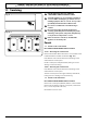
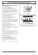
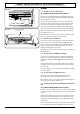
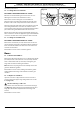
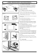
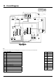
Table Of Contents
- U111305 cover [Aus]
- U111305-01 [AUS]
- 1. Before You Start...
- 2. Cooker Overview
- 3. 3 button clock
- 4. Cooking Tips
- 5. Cooking Table
- 6. Cleaning your cooker
- 7. Troubleshooting
- 8. Service and Spares
- 9. Installation
- Safety Requirements and Regulations
- Provision of Ventilation
- Location of Cooker
- Conversion
- Positioning the Cooker
- Moving the Cooker
- Lowering the Two Rear Rollers
- Completing the Move
- Fitting the Stability Bracket and Chain
- Fitting the Oven Burner Trim
- Gas Connection
- Natural Gas
- Propane
- Pressure Testing
- Electrical Connection
- Earth Continuity Check
- Polarity Check
- Final Checks
- Final Fitting
- Customer Care
- 10. Conversion to LP Gas
- 11. Servicing
- 12. Circuit Diagram
- 13. Technical Data

43
12. Circuit Diagram
Spark
Spark
11
Pactrol
Micro-gas
N L
Con6 Con7 JT1 JT2
11
Pactrol
Micro-gas
N L
Con6 Con7 JT1 JT2
A
BC
D
E
N
M
F
J
I
K
L
H
2
2a
NA
1 2 3 4 5 6 E
Test
switch
For manufacturing
test purposes only
G
b
b
br
br
b
b
v
b
b
v
yy
br
br
w
br
v
v
or br
b
w
bbbr br
Sensor
r
r
y
y
br
b
b
b
or
y
Sensor
br
b
b
br
br
b
c
b
c
c
c
c
c
br
br
br
br
bbb
br
br
br
br
br
br
r
r
b
b
b
br
Code Description
A
Right-hand oven thermostat switch
B
Left-hand oven thermostat switch
C
Oven light switch
D
Clock
E
Ignition switch
F
Right-hand oven light bulb
G
Spark generator
H
Left-hand oven light bulb
I
Flame safeguard unit
J
Flame safeguard unit
K
Solenoid assembly
L
Solenoid assembly
M
Cooling fan
N
Cooling fan thermal preset
Key
The connections shown in the circuit diagram are for single-phase. The ratings are for 230 V 50 Hz.
Code Colour
b Blue
br Brown
bk Black
or Orange
r Red
v Violet
w White
y Yellow
g/y Green/yellow
gr Grey