USER GUIDE & INSTALLATION INSTRUCTIONS Classic 110 Gas Australia U111305-01
Contents 1. 2. 1 8. Service and Spares 24 Personal Safety 1 Electrical Connection Safety 2 9. Installation 25 If You Smell Gas 2 Peculiar Smells 2 Cooling Fan 2 Ventilation 3 Maintenance 3 Grill/Glide-out Grill™ Care 5 Cooker Care 5 Cleaning 5 Before You Start...
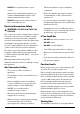
1. Before You Start... Your cooker should give you many years of trouble-free cooking if installed and operated correctly. It is important that you read this section before you start. Personal Safety This appliance is for cooking purposes only. It must not be used for other purposes, for example heating a room. Using it for any other purpose could invalidate any warranty or liability claim. Besides invalidating claims this wastes fuel and may overheat the control knobs.
• DO NOT use a steam cleaner on your cooker. • Always keep combustible materials, e.g. curtains, and flammable liquids a safe distance away from the cooker. • Make sure that the gas supply is turned on and that the cooker is wired in and switched on. • DO NOT spray aerosols in the vicinity of the cooker while it is on. • In your own interest and that of safety, it is law that all gas appliances be installed by a qualified person(s).
by the manufacturer of the cooking appliance or indicated by the manufacturer of the appliance in the instructions for use as suitable or hob guards incorporated in the appliance. The use of inappropriate guards can cause accidents. the grill or ovens are in operation the fan will run to cool the fascia and control knobs. Ventilation The use of a cooking appliance results in the production of heat and moisture in the room in which it is installed.
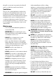
along the back of the cooker) for warming plates, dishes, drying tea towels or softening butter. Fig. 1.1 • DO NOT use water on grease fires and never pick up a flaming pan. Turn the controls off and then smother a flaming pan on a surface unit by covering the pan completely with a well fitting lid or baking tray. If available, use a multi-purpose dry chemical or foam-type fire extinguisher. • DO NOT modify this appliance.
underneath it, otherwise the knobs may become hot. door glass since they can scratch the surface, which may result in shattering of the glass. • Make sure the shelves are pushed firmly to the back of the oven. DO NOT close the door against the oven shelves. • DO NOT use aluminium foil to cover shelves, linings or the oven roof. • When the oven is on, DO NOT leave the oven door open for longer than necessary, otherwise the control knobs may become very hot.
6 • Before you remove any of the grill parts for cleaning, make sure that they are cool or use oven gloves. • DO NOT use any abrasive substances on the grill and grill parts. • DO NOT put the side runners in a dishwasher. • DO NOT put the burner heads in a dishwasher. • NEVER use caustic or abrasive cleaners as these will damage the surface. • DO NOT use steel wool, oven cleaning pads or any other materials that will scratch the surface. • NEVER store flammable materials in the drawer.
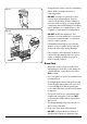
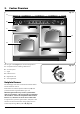
2. Cooker Overview Fig. 2.1 A B C E M D F The 110 gas cooker (Fig. 2.1) has the following features: Fig. 2.2 A. 6 hotplate burners including a wok burner B. A control panel C. A grill D. Left-hand oven E. Right-hand oven F. A storage drawer Hotplate Burners The drawing by each of the central knobs indicates which burner that knob controls. Each burner has a Flame Supervision Device (FSD) that prevents the flow of gas if the flame goes out.
The igniter should spark and light the gas. Keep holding the knob pressed in to let the gas through to the burner for about ten seconds. Fig. 2.3 If, when you let go of the control knob, the burner goes out, then the FSD has not been bypassed. Turn the control knob to the OFF position and wait for one minute before you try again, this time making sure to hold in the control knob for slightly longer. Adjust the flame height to suit by turning the knob counterclockwise (Fig. 2.3).
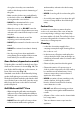
The Wok Cradle (optional extra) Fig. 2.9 The wok cradle is designed to fit a 35 cm wok. If you use a different wok, make sure that it fits the cradle. Woks vary very widely in size and shape. It is important that the wok sits down on the pan support – however, if it is too small, the cradle will not support the wok properly (Fig. 2.9). The cradle should be used on the triple ring wok burner only.
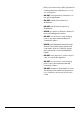
The Grill Fig. 2.15 n CAUTION: This appliance is for cooking purposes only. It must not be used for other purposes, for example room heating. n CAUTION: Accessible parts may be hot when the grill is in use. Young children should be kept away. Open the door and, using the handle, pull the grill pan forward (Fig. 2.15). ArtNo.331-0001Grill pan pulled forwards The burner does not glow red when in use; food cooks from the heat of the flame.
The Ovens ArtNo.323-0003 Bray gas oven burner flame The clock must be set to the time of day before the ovens will work. See the following section on ‘The Clock’ for instructions on setting the time of day. Fig. 2.19 References to ‘left-hand’ and ‘right-hand’ ovens apply as viewed from the front of the appliance. Both ovens are gas ovens. Note: Please remember that all cookers vary so temperatures in your new ovens may differ to those in your previous cooker. Fig. 2.
Meat Beef Rare 60 °C / 140 °F Medium 71 °C / 160 °F Well done 77 °C / 170 °F Lamb Pork Cover dishes tightly with a lid or foil to prevent evaporation and transfer of flavour. Temperature Once the oven has been loaded and the ‘S’ setting is in operation resist the temptation to open the oven door. Heat will be lost and the cooking time extended. A meat thermometer is recommended for checking that a joint or poultry is sufficiently cooked. Insert the probe through the thickest part of the meat.
Accessories Fig. 2.25 Oven Shelves Shelf guard The cooker is supplied with 4 flat shelves (Fig. 2.25). The oven shelves can be easily removed and refitted. Pull the shelf forward until the back of the shelf is stopped by the shelf stop bumps in the oven sides (Fig. 2.26). Front Lift up the front of the shelf so the back of the shelf will pass under the shelf stop and then pull the shelf forward (Fig. 2.27). Fig. 2.
3. 3 button clock Setting the time The clock must be set to the time of day before the oven will work Reset the minute minder Step. 1 Note: The cook symbol [ ] remains visible during normal operation. Step. 1 ArtNo.306-0001 - 3-button clock ArtNo.306-0001 - 3-button clock Step. 2 Step. 2 Press the [+] and [-] buttons simultaneously. Press either [+] or [-] buttons. ArtNo.306-0001 - 3-button clock ArtNo.
To start and stop the oven automatically (main oven only) Step. 1 AUTO is showing, but you want to revert to manual cooking (main oven only) Press [M] button again until current time is diplayed. Press either [+] or [-] buttons ArtNo.306-0001 - 3-button clock Step. 2 ArtNo.306-0001 - 3-button clock Set the length of time you want the oven to cook for. ArtNo.306-0001 - 3-button clock Changing the frequency of the alarm Step. 1 Press [M] button again until current time is diplayed.
4. Cooking Tips Tips on cooking with the timer General oven tips If you want to cook more than one dish, choose dishes that require approximately the same cooking time. However, dishes can be ‘slowed down’ slightly by using small containers and covering them with aluminium foil, or ‘speeded up’ slightly by cooking smaller quantities or placing them in larger containers. The wire shelves should always be pushed firmly to the back of the oven.
5. Cooking Table The oven control settings and cooking times given in the table below are intended to be used as a guide only. Individual tastes may require the temperature to be altered to provide a preferred result. Food is cooked at lower temperature in a fan oven than in a conventional oven. When using recipes, reduce the fan oven temperature by 10 °C and the cooking time by 5-10 minutes. The temperature in the fanned oven does not vary with height in the oven so you can use any shelf.
6. Cleaning your cooker Essential Information Fig.6.1 A Isolate the electricity supply before carrying out any thorough cleaning. Allow the cooker to cool. C n NEVER use paint solvents, washing soda, caustic cleaners, biological powders, bleach, chlorine based bleach cleaners, coarse abrasives or salt. n DO NOT mix different cleaning products – they may react together with hazardous results.
Glide-out Grill n Before you remove any of the grill parts for cleaning. make sure that they are cool, or use oven gloves. n DO NOT use any abrasive substances. Fig.6.5 The face of the grill burner will darken with use – this is perfectly normal. Any fat or grease will burn off. Do not try to clean it – the small holes could get blocked and may affect the burner performance. ArtNo.331-0001Grill pan pulled forwards ArtNo.
Fig.6.10 After cleaning, carefully refit the outer door panel and replace the side fixing screws. Thermostat temperature sensor n DO NOT use harsh abrasive cleaners or sharp metal scrapers to clean the oven door glass since they can scratch the surface, which may result in shattering of the glass. Ovens Cleaning is easier if carried out while the oven is still warm. Before cleaning, cover the burner to prevent the burner holes becoming blocked.
Cleaning Table Cleaners listed (Table 6.1) are available from supermarkets or electrical retailers as stated. For enamelled surfaces use a cleaner that is approved for use on vitreous enamel. Regular cleaning is recommended. For easier cleaning, wipe up any spillages immediately. Hotplate Part Finish Recommended Cleaning Method Hob top (including burner heads and caps) Enamel, stainless steel, aluminium Hot soapy water, soft cloth. Any stubborn stains remove gently with a nylon scourer.
7. Troubleshooting What cleaning materials are recommended for the cooker? The knobs get hot when I use the oven or the grill. Can I avoid this? See the ‘Cleaning’ section for recommended cleaning materials. Yes, this is caused by heat rising from the oven or the grill, and heating them up. Do not leave the oven door open. n Never use caustic or abrasive cleaners as these will damage the surface. Make sure that the grill pan is pushed right back to the ‘back stop’ when grilling.
Oven not coming on Fig. 7.1 Is the power on? Is the clock illuminated? If not, there may be something wrong with the power supply. Is the cooker supply on at the isolator switch? Has the time of day been set? The timed oven is not coming on when automatic cooking Has the oven knob been left in the ‘OFF’ position by mistake? Fig. 7.
INSTALLATION Check the appliance is electrically safe when you have finished. 8. Service and Spares Firstly, please complete the appliance details below and keep them safe for future reference – this information will enable us to accurately identify the particular appliance and help us to help you. Filling this in now will save time and inconvenience if you later have a problem with the appliance. It may also be of benefit to keep your purchase receipt with this leaflet.
INSTALLATION Check the appliance is gas sound when you have finished. 9. Installation Safety Requirements and Regulations n Provision of Ventilation This appliance is not connected to a combustion products evacuation device. Particular attention shall be given to the relevant requirements regarding ventilation in accordance with AS/NZS 5601. Please read the Before you start... chapter, before you begin any installation and maintenance work on this appliance.
INSTALLATION Check the appliance is gas sound when you have finished. You will need the following equipment to complete the cooker installation satisfactorily: Checking the Parts: Pan supports • Flexible gas hose. Plinth • Gas pressure tester/manometer. • Multimeter: For electrical checks. ArtNo.110-0002 110 pan supports You will also need the following tools: 1. Electric drill 2. Masonry drill bit (only required if fitting the cooker on a stone or concrete floor) 3.
INSTALLATION Check the appliance is gas sound when you have finished. Positioning the Cooker Fig. 9.1 The diagram (Fig. 9.1) shows the minimum recommended distance from the cooker to nearby surfaces as given in AS/NZS 5601. Where the appliance is installed next to cabinetry, the cabinet material must be capable of withstanding 70°C. If this appliance is installed near vinyl wrapped surfaces, use an installation kit available from the vinyl-wrap supplier.
INSTALLATION Check the appliance is gas sound when you have finished. Moving the Cooker Fig. 9.3 n On no account try and move the cooker while it is plugged into the electricity supply. n The cooker is very heavy, so take great care. We recommend that two people manoeuvre the cooker. Make sure that the floor covering is firmly fixed, or removed, to prevent it being disturbed when moving the cooker around.
INSTALLATION Check the appliance is gas sound when you have finished. Fitting the Stability Bracket and Chain n Fig. 9.6 A stability bracket and chain MUST be fitted when the cooker is connected to a flexible gas supply. Unless properly installed, the cooker could be tipped by leaning on the door. Injury might result from spilled hot liquids or from the cooker itself.
INSTALLATION Check the appliance is gas sound when you have finished. Repositioning Following Connection Fig. 9.10 If you need to move the cooker once it has been connected then you need to unplug it and, having gripped under the fascia panel and lifted the front of the cooker slightly (Fig. 9.5), you need to check behind the cooker to make sure that the gas hose is not caught.
INSTALLATION Check the appliance is gas sound when you have finished. Propane • Active: To the terminal marked A, or coloured RED or BROWN. This cooker is supplied ready for use on natural gas. A conversion kit for Propane as is supplied with the cooker – see the ‘Conversion to Propane Gas’ section. When wiring the plug make sure that all strands of wire are retained in each terminal.
INSTALLATION Check the appliance is gas sound when you have finished. Fixed Wiring Fig. 9.13 n Disconnect from the mains supply. For connection to fixed wiring, i.e. flexible conduit, Remove the electrical terminal cover on the back panel (Fig. 9.13). Remove the M4 screw securing the reducer plates to the conduit box (Fig. 9.14). Fit the conduit box to the cooker using the two M5 screw fittings located at the top of the box and the M4 screw (Fig. 9.15). The conduit box cover is reversible.
INSTALLATION Check the appliance is gas sound when you have finished. Final Fitting Fig. 9.18 Fitting the Handles and Handrail Remove the 4 mm Allen screws from the doors (Fig. 9.18). Fit the door handles and secure using the 4 mm screws. n ArtNo.215-0026 - Handle gaskets fixed The handles should be above the fixings. Remove the 4 mm Allen screws from the top corners of the fascia (Fig. 9.19). Fit the handrail in position and secure using the 4 mm screws. Fig. 9.
WARNING – SERVICING TO BE CARRIED OUT ONLY BY AN AUTHORISED PERSON Disconnect from electricity and gas before servicing. Check appliance is safe when you have finished. 10. Conversion to LP Gas Conversion from Natural Gas (1.0 kPa) to LPG X Propane (2.54 kPa) Fig. 10.1 A B ArtNo.311-0010 Injectors A – Jet, B – Jet n A suitably competent person must perform the conversion.
WARNING – SERVICING TO BE CARRIED OUT ONLY BY AN AUTHORISED PERSON Disconnect from electricity and gas before servicing. Check appliance is safe when you have finished. Grill Fig. 10.4 Injector Lift up the spring retaining the grill holder and slide the jet holder out of the burner venturi (Fig. 10.4). Remove the grill jet from the adaptor and fit a new jet; see the ‘Technical Data’ for the correct jets. Refit the jet holder back into the burner venturi. ArtNo.
WARNING – SERVICING TO BE CARRIED OUT ONLY BY AN AUTHORISED PERSON Disconnect from electricity before servicing. Check appliance is safe when you have finished. 11. Servicing Fig. 11.1 Art No 215-0028 - Handrail fascia fixings Fig. 11.2 n BEFORE SERVICING ANY GAS CARRYING COMPONENTS TURN OFF THE GAS SUPPLY n Check the appliance is gas sound after completion of service. When checking for gas leaks do not use washing up liquid – this can corrode.
WARNING – SERVICING TO BE CARRIED OUT ONLY BY AN AUTHORISED PERSON Disconnect from electricity before servicing. Check appliance is safe when you have finished. Hotplate 2.5 To Replace a Hotplate Burner 2.1 To Remove the Hotplate DISCONNECT FROM THE ELECTRICITY SUPPLY. Pull the cooker forward to gain access to the rear. Remove the hotplate tray (see 2.1). The burners (except the right-hand wok burner) are mounted on support struts. For these burners, disconnect the burner feed pipes at the burner.
WARNING – SERVICING TO BE CARRIED OUT ONLY BY AN AUTHORISED PERSON Disconnect from electricity before servicing. Check appliance is safe when you have finished. Controls Fig. 11.3 3.1. To Replace the Ignition or Light Switch DISCONNECT FROM THE ELECTRICITY SUPPLY. Remove the control panel (see 1.1). Note: The old switch may be destroyed during removal. Remove the old switch from its bezel by gripping the switch body behind the control panel and twisting sharply.
WARNING – SERVICING TO BE CARRIED OUT ONLY BY AN AUTHORISED PERSON Disconnect from electricity before servicing. Check appliance is safe when you have finished. Grill Spring clip BEFORE SERVICING ANY GAS CARRYING COMPONENTS, TURN OFF THE GAS SUPPLY. Fig. 11.4 4.1 To Change the Grill Control Tap DISCONNECT FROM THE ELECTRICITY SUPPLY. Remove the control panel (see 1.1). Lift up the right-hand hotplate tray front (see 2.1).
WARNING – SERVICING TO BE CARRIED OUT ONLY BY AN AUTHORISED PERSON Disconnect from electricity before servicing. Check appliance is safe when you have finished. Ovens Fig. 11.6 5.1 To Remove an Oven Thermostat DISCONNECT FROM THE ELECTRICITY SUPPLY. Remove the right-hand hotplate tray (see 2.1); for the lefthand oven remove the left-hand side panel (see 1.2). Open the appropriate oven door. Fig. 11.7 Unclip the thermostat phial from the clips at the front of the oven roof.
WARNING – SERVICING TO BE CARRIED OUT ONLY BY AN AUTHORISED PERSON Disconnect from electricity before servicing. Check appliance is safe when you have finished. Check the performance. Fig. 11.8 5.6 To Change the Oven Solenoids Fig. 11.9 DISCONNECT FROM THE ELECTRICITY SUPPLY. Move the cooker forward to gain access to the rear. See ‘Moving Your Cooker’ in the installation section. Remove the screws securing the cover and lift clear.
WARNING – SERVICING TO BE CARRIED OUT ONLY BY AN AUTHORISED PERSON Disconnect from electricity before servicing. Check appliance is safe when you have finished. Fig. 11.10 6.3 To Adjust an Oven Door Angle Centreline of hinge pin The bottom hinge of either oven door can be adjusted to alter the angle of the door (Fig. 11.10). Loosen the bottom hinge fixing screws and use the notch and a flat bladed screwdriver to move the position of the hinge to set the hinge position (Fig. 11.11).
12.
13. Technical Data ArtNo.105-0008 - Technical data - 90 induction - Elan This cooker is designed for use on Natural Gas, although a conversion for LP (LPG X Propane (2.54 kPa)) gas is included. INSTALLER: Please leave these instructions with the User. DATA BADGE LOCATION: Cooker back, serial number repeater badge below oven door opening. COUNTRY OF DESTINATION: Australia.
Clarence Street, Royal Leamington Spa, Warwickshire, CV31 2AD, England. www.falconworld.