USER GUIDE & INSTALLATION INSTRUCTIONS Classic / Professional+ 110 Induction Australia U110896 - 04
Contents 1. 2. Before You Start... 1 7. Cleaning your cooker 24 Personal Safety 1 Electrical Connection Safety 2 8. Troubleshooting 28 Peculiar Smells 3 9.
ii
1. Before You Start... Your cooker should give you many years of trouble-free cooking if installed and operated correctly. It is important that you read this section before you start. Personal Safety • DO NOT operate this appliance before reading the instruction booklet. • DO NOT place articles on or against this appliance. • DO NOT operate with panels, covers or guards removed from this appliance. • The cooker should not be placed on a base.
Electrical Connection Safety Fig. 1.1 THE APPLIANCE MUST BE n WARNING: EARTHED. The cooker is preset for a single-phase earthed electrical connection. It is essential to install a multi-pole circuit breaker that completely disconnects the appliance from the mains, with a minimum contact break distance of 3 mm. ArtNo.132-0001 - 1 phase 240Vac 50Hz 1-phase 230 VAC 50 Hz The total electrical load of the appliance is approximately 15 kW.
• The appliance must be installed in accordance with the regulations in force and only in a well ventilated space. Maintenance • It is recommended that this appliance is serviced annually. • Failure to install the appliance correctly could invalidate any warranty or liability claims and lead to prosecution. • • DO NOT install the appliance on a platform. WARNING: Before replacing the bulb, turn off the power supply and make sure that the oven is cool.
n NEVER try to extinguish a fire with water, but switch off the appliance and then cover the flame e.g. with a lid or a fire blanket. • NEVER leave a chip pan unattended. Always heat fat slowly, and watch as it heats. Deep fry pans should be only one third full of fat. • WARNING: Danger of fire: do not store Induction care • of this hob comply with the applicable European standards on electromagnetic interference.
• Take care NOT to scratch the surface when placing cookware on the glass panel. • Only certain types of glass, glass-ceramic, earthenware or other glazed containers are suitable for hotplate cooking; others may break because of the sudden change in temperature. NEVER cook directly on the hob surface (Fig. 1.4). Fig. 1.3 Fig. 1.4 Fig. 1.5 • DO NOT leave the hob zones switched on ArtNo.312-0001 Not cooking surface unless being used for cooking. • DO NOT stand or rest heavy objects on the hob.
Fig. 1.8 • We recommend that you avoid wiping any surface unit areas until they have cooled and the indicator light has gone off. Sugar spills are the exception to this (see ‘Cleaning your Cooker’). After cleaning, use a dry cloth or paper towel to remove any cleaning cream residue. • The ceramic surface should be washed after use in order to prevent it from becoming scratched or dirty. However, you should clean the hob with caution as some cleaners can produce noxious fumes if applied to a hot surface.
• • • Make sure the shelves are pushed firmly to the back of the oven. DO NOT close the door against the oven shelves. DO NOT use aluminium foil to cover shelves, linings or the oven roof. When the oven is on, DO NOT leave the oven door open for longer than necessary, otherwise the control knobs may become very hot. • DO NOT use the timed oven if the adjoining oven is already warm. • DO NOT place warm food in the oven to be timed. • DO NOT use a timed oven that is already warm.
Cleaning • Isolate the electricity supply before carrying out any thorough cleaning. Allow the cooker to cool. • In the interests of hygiene and safety, the cooker should be kept clean at all times as a build up in fats and other food stuff could result in a fire. • Clean only the parts listed in this guide. • Clean with caution. If a wet sponge or cloth is used to wipe spills on a hot surface, be careful to avoid steam burns. Some cleaners can produce noxious fumes if applied to a hot surface.
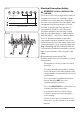
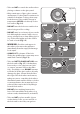
2. Cooker Overview ArtNo.025-0005 - Overview - 90 induction - 2 button clock & GO grill Fig. 2.1 A B C E D ArtNo.190-0002 - 110 Induction annotated GENERIC F Your 110 induction cooker (Fig. 2.1) has the following features: Fig. 2.2 A. 5 induction cooking zones B. Control panel C. A separate Glide-out Grill™ D. A programmable fan oven E. Fan oven F. Storage Drawer The Hob Fig. 2.3 Use only pans that are suitable for induction hobs.
you will see a small gap in the middle. When they heat up the metal expands and lies flat on the cooking surface. Fig. 2.4 Max: 1.85 kW Boost: 2.5 kW Max: 1.85 kW Boost: 3.0 kW Zone 1 Max: 1.85 kW Boost: 2.5 kW Zone 3 Make sure that the base of the pan is clean and dry to prevent any residue burning onto the hob panel. This also helps prevent scratches and deposits. Always use pans that are the same size as (or slightly larger than) the areas marked on the hob.
Residual Heat Indicator, H After use, a cooking zone will remain hot for a while as heat dissipates. When a cooking zone is switched off the residual heat indicator symbol [H ], will appear in the display. This shows that the cooking zone temperature is above 60 °C and may still cause burns. Once the temperature has dropped to below 60 °C the [H ] will go out.
Low Temperature Setting, L1/L2 Maximum Operating Time Power Level L1 and L2 2 hours 1 6 hours 2 6 hours 3 5 hours 4 ArtNo.051-0002 - Min pan diameter 5 hours 5 4 hours 6 1.5 hours 7 1.5 hours 8 1.5 hours 9 1.5 hours Power Boost 10 minutes n Each cooking area is equipped with 2 low temperature settings: • • L1 will maintain a temperature of about 40 °C – ideal for gently melting butter or chocolate.
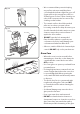
The Glide-out Grill n CAUTION: This appliance is for cooking purposes only. It must not be used for other purposes, for example room heating. n CAUTION: Accessible parts may be hot when the grill is in use. Young children should be kept away. Fig. 2.9 Open the door and pull the grill pan carriage forward using the handle (Fig. 2.9). ArtNo.331-0001Grill pan pulled forwards The grill has two elements that allow either the whole area of the pan to be heated or just the right-hand half. Fig. 2.
The Ovens Fig. 2.12 The clock must be set to the time of day before the programmable oven will work. See the following section on ‘The Clock’ for instructions on setting the time of day. References to ‘left-hand’ and ‘right-hand’ ovens apply as viewed from the front of the appliance. ArtNo.235-0004 Classic DL oven 1 The left-hand oven is a rogrammable fan oven, while the right-hand oven is a fan oven. The Fan Oven Fan ovens circulate hot air continuously, which means faster, more even cooking.
Accessories Fig. 2.15 Oven Shelves The oven shelves (Fig. 2.15) are retained when pulled forward but can be easily removed and refitted. Pull the shelf forward until the back of the shelf is stopped by the shelf supports (Fig. 2.16). Lift up the front of the shelf so the back of the shelf will pass under the shelf stop and then pull the shelf forward (Fig. 2.17). To refit the shelf, line up the shelf with a groove in the oven shelf supports and push the shelf back until the ends hit the shelf stop.
Glide-out Oven Shelf (optional) Fig. 2.22 A glide-out oven shelf is available for either oven (Fig. 2.22). Note: The Handyrack must be removed before fitting the glide-out shelf. The rungs on the shelf supports are in pairs. The glide-out shelf runners can be fitted to any pair except the top. To fit the glide-out shelf runners Hook the rear of the runner over the top rung of a pair of shelf supports. Then hook the front of the runner onto the same rung. Push to clip under the bottom rung (Fig. 2.23).
3. 2 Button - rotary clock Fig. 3.1 The clock must be set to the time of day before the oven will work. ArtNo.300-0005 2BC minute minder setting C Setting the Clock D A B 1. Once the cooker is connected and switched on, the display will start to flash. 2. To set the time, turn the Timer (A) knob to the Clock (C) setting and back to the Manual (D) position. The centre dot will flash indicating the time can be set. Turn the Adjusting (B) knob either clockwise or counterclockwise (Fig. 3.
To stop the oven at a specific time of day Fig. 3.5 You have set the required temperature and function mode and you would like the oven to automatically stop. TOP TIP G Make a note of the current time so you do not forget. 1. A B Turn the Timer (A) knob to the Stop Time (G) setting. ‘AUTO’ will show in the display (Fig. 3.5). 2. Turn the Adjusting (B) knob to the amount of cooking time required. The display will show the current time plus the additional cooking time you have set (Fig. 3.6). 3.
To start and stop the oven automatically Fig. 3.9 The timer allows you to automatically start and stop by a combination of the length of the cooking time and the stop time. Giving you the flexibility to cook casseroles etc while you are out. You cannot set the actual start time. F A B Fig. 3.10 G A B 1. Turn the Timer (A) knob to the Cook Time (F) setting. Turn the Adjusting (B) knob clockwise to set the length of the cooking time required (Fig. 3.9). 2.
4. 3 Button clock Using the clock Fig. 4.1 You can use the clock to turn the programmable oven on and off. The clock must be set to the time of day before the oven will work. NOTE: When using the timer functions, first set the clock as required before setting the oven temperature. ArtNo.306-0001 - 3-button clock The oven can be switched on when the cook symbol [ ] is displayed. This symbol remains visible during normal operation. Fig. 4.2 Setting the clock 1. The LCD clock is shown in (Fig. 4.1).
3. When the ‘stop time’ is reached an alarm will sound and the oven will stop working. The word ‘AUTO’ will flash on the display (Fig. 4.6). 4. Press any button to stop the alarm and return to manual cooking. If the alarm is not stopped, it will stop automatically after 7 minutes. Fig. 4.7 ArtNo.306-0001 - 3-button clock To start and then stop the programmable oven Set the programmable oven to automatically start and stop using a combination of the ‘cook period’ and ‘stop time’. Fig. 4.
5. Cooking Tips Hints on Using Your Induction Cooker General Oven Tips If you have not used an induction cooker before please be aware of the following: The wire shelves should always be pushed firmly to the back of the oven. • Make sure that the pans you have or buy are suitable for use on the induction hob. Stainless steel, enamelled steel or cast iron is ideal. Double check before you buy pans – they must have bases that would attract a magnet.
6. Cooking Table The oven control settings and cooking times given in the table below are intended to be used as a guide only. Individual tastes may require the temperature to be altered to provide a preferred result. Food is cooked at lower temperature in a fan oven than in a conventional oven. When using recipes, reduce the fan oven temperature by 10 °C and the cooking time by 5-10 minutes. The temperature in the fan oven does not vary with height in the oven so you can use any shelf.
7. Cleaning your cooker DocNo.040-0004 - Cleaning - 110 ceramic GENERIC Fig. 7.1 ArtNo.312-0010 Cleaning; scraping the ceramic hob n Isolate the electricity supply before carrying out any major cleaning. Then allow the cooker to cool. n NEVER use paint solvents, washing soda, caustic cleaners, biological powders, bleach, chlorine based bleach cleaners, coarse abrasives or salt. n DO NOT mix different cleaning products – they may react together with hazardous results.
Grills Fig. 7.2 ArtNo.331-0003 Grill frame out, no pan The grill pan and trivet should be washed in hot soapy water. After grilling meats or any foods that soil, leave to soak for a few minutes immediately after use. Stubborn particles may be removed from the trivet using a nylon brush. Alternatively, the grill pan can be washed in a dishwasher. n Before you remove any of the grill parts for cleaning, make sure that they are cool, or use oven gloves. n DO NOT use any abrasive substances.
Glass fronted door panels Fig. 7.5 The oven door front panels can be taken off so that the glass panels can be cleaned. Move the cooker forward to gain access to the sides (see the ‘Moving the Cooker’ section under ‘Installation’). Open the oven door slightly and remove the front panel fixing screws from the door sides, two each side (Fig. 7.5). Carefully lift off the outer door panel. The inside face of the glass panels can now be cleaned – take care not to disturb or wet the door insulation. ArtNo.
Cleaning table Cleaners listed (Table 7.1) are available from supermarkets or electrical retailers as stated. For enamelled surfaces use a cleaner that is approved for use on vitreous enamel. Regular cleaning is recommended. For easier cleaning, wipe up any spillages immediately. Hotplate Part Finish Recommended Cleaning Method Hob top Enamel or stainless steel Hot soapy water, soft cloth. Any stubborn stains remove gently with a nylon scourer.
8. n Troubleshooting DocNo.050-0001 - Troubleshooting - Induction GENERIC Interference with and repairs to the hob MUST NOT be carried out by unqualified persons. Do not try to repair the hob as this may result in injury and damage to the hob. Please arrange for repair by a suitably competent person. Poor performance In the unlikely event that, after installation, the appliance does not perform correctly please contact your distributor (see “Service and Spares” on page 31).
Food is cooking too slowly, too quickly, or burning Fig. 8.1 Cooking times may differ from your previous oven. Check that you are using the recommended temperatures and shelf positions – see the oven cooking guide. Then adjust the settings according to your own individual tastes. The oven light is not working The bulb has probably blown. You can buy a replacement bulb (which is not covered under the guarantee) from most electrical stores. Fig. 8.2 Ask for a 40 W - 230 V halogen lamp (G9) (Fig. 8.1).
Power failure In the event of a failure in the electrical supply, remember to reset the clock so that the timed oven continues to operate. The timed oven is not coming on when turned on manually Is the power on? Is the clock illuminated? If not, there may be something wrong with the power supply.
INSTALLATION Check the appliance is electrically safe when you have finished. 9. Service and Spares Firstly, please complete the appliance details below and keep them safe for future reference – this information will enable us to accurately identify the particular appliance and help us to help you. Filling this in now will save time and inconvenience if you later have a problem with the appliance. It may also be of benefit to keep your purchase receipt with this leaflet.
INSTALLATION Check the appliance is electrically safe when you have finished. You will need the following equipment to complete the cooker installation satisfactorily: Multimeter (for electrical checks). You will also need the following tools: 1. Steel tape measure 2. Cross-head screwdriver 3. Flat-bladed screwdriver 4. Spirit level 5. Pencil 6. Adjustable spanner 7. 3 mm and 4 mm Allen keys 8.
INSTALLATION Check the appliance is electrically safe when you have finished. Positioning the Cooker Fig. 9.1 Fig. 9.1 and Fig. 9.2 shows the minimum recommended distance from the cooker to nearby surfaces. 75mm min Where the appliance is installed next to cabinetry, the cabinet material must be capable of withstanding 70°C. If this appliance is installed near vinyl wrapped surfaces, use an installation kit available from the vinyl-wrap supplier.
INSTALLATION Check the appliance is electrically safe when you have finished. Lowering the Two Rear Rollers Fig. 9.5 To adjust the height of the rear of the cooker, first fit a 13 mm spanner or socket wrench onto the hexagonal adjusting nut (Fig. 9.5). Rotate the nut – clockwise to raise – counterclockwise to lower. Make 10 complete (360°) turns clockwise. Make sure you lower BOTH REAR ROLLERS. Completing the Move Unfold the rear edge of the cardboard base tray.
INSTALLATION Check the appliance is electrically safe when you have finished. Electrical Connection Fig. 9.11 This appliance must be installed by a qualified electrician to comply with current AS/NZS 3000 Wiring Rules and regulations in force. Make sure that the mains characteristics (voltage, nominal, power, etc.) match the ratings indicated on the data plate affixed to the cooker. ArtNo.132-0001 - 1 phase 240Vac 50Hz The cooker is preset for a single-phase earthed electrical connection.
INSTALLATION Check the appliance is electrically safe when you have finished. Connection in New Zealand Fig. 9.13 Type of cord in accordance with IEC 60227 with a minimum rating of 90°C. Cord size recommended for this application is 3 x 10 mm², three-core cable (Power cables may be sized to take into account the coincidence factor AS/NZS 60335.2.6:2014). Rating of the plug is 32 Amp, in accordance with AS/NZS 3112.
INSTALLATION Check the appliance is electrically safe when you have finished. Final Checks Fig. 9.17 After completing installation check operation of the appliance: Hob Check Check each cooking zone in turn. Be sure to use pans of the correct size and material. ArtNo.215-0026 - Handle gaskets fixed Grill Check Turn on the grill control and check that the grill heats up. Fig. 9.18 Oven Check Set the clock as described earlier, and then turn on the ovens.
WARNING – SERVICING TO BE CARRIED OUT ONLY BY AN AUTHORISED PERSON Disconnect from electricity before servicing. Check appliance is safe when you have finished. 10. Servicing Fig. 10.1 n Disconnect the cooker from the electricity supply before servicing, particularly before removing any of the following: control panel, side panels, ceramic hob, or any of the electrical components or cover boxes. n Before reconnection, check that the appliance is electrically safe. ArtNo.
WARNING – SERVICING TO BE CARRIED OUT ONLY BY AN AUTHORISED PERSON Disconnect from electricity before servicing. Check appliance is safe when you have finished. 3. Controls 3.1 To Replace the Light Switch DISCONNECT FROM THE ELECTRICITY SUPPLY. Remove the control panel (see 1.1). Note: The old switch may be destroyed during removal. Remove the old switch from its bezel by gripping the switch body behind the control panel and twisting sharply.
WARNING – SERVICING TO BE CARRIED OUT ONLY BY AN AUTHORISED PERSON Disconnect from electricity before servicing. Check appliance is safe when you have finished. 5. Ovens Fig. 10.2 5.1 To Replace an Oven Thermostat DISCONNECT FROM THE ELECTRICITY SUPPLY. Lift the ceramic hob and remove the control panel (see 1.1 & 2.1). Open the oven door. Remove the oven furniture. For the right-hand oven, remove the thermostat phial cover (two screws). Unclip the thermostat phial from the clips in the oven back.
WARNING – SERVICING TO BE CARRIED OUT ONLY BY AN AUTHORISED PERSON Disconnect from electricity before servicing. Check appliance is safe when you have finished. fan blade and remove the centre nut (left-hand thread) two brass washers, fan blade and circlip. Unscrew the fan retaining nuts and washers (three off each) and lift the fan away from the rear of the cooker. Fit the new fan and reassemble in reverse order. Fig. 10.4 Fig. 10.5 Check the operation of the oven. 6. Doors 2 1 6.
WARNING – SERVICING TO BE CARRIED OUT ONLY BY AN AUTHORISED PERSON Disconnect from electricity before servicing. Check appliance is safe when you have finished. Fig. 10.9 6.5 To Change the Main Oven Door Latch Fig. 10.10 Remove the outer door panel (see 12). Remove screws ‘B’ that hold the latch assembly to the inner door panel (Fig. 10.9). Fit the new catch and reassemble in reverse order. ArtNo.320-0004 Oven door keep Verify the door operation. 6.
11. Circuit Diagram Hob INDUCTION UNIT E Earth 5 N(6) On Terminal Block 4 N(4) On Terminal Block 3 2 1 HOB DISPLAY w/br w/br L(2) L(3) On Terminal Block 1 INTERFACE 2 BOARD 5 3 4 w/br w/br 1 2 w/br 5 3 4 Key The connections shown in the circuit diagram are for single-phase. The ratings are for 230 V 50 Hz.
Oven r J v bk br br br r b v K y br A2 bk C v b br b b br r r v r y J r r 2 P2 or y B1 1 P1 P095199 F bk B4 br b g/y br y D2 br br y J b y y b B2 B3 b b y y or v y P2 br D1 g/y P1 v P095199 1 y v bk A1 P2 P1 P095199 A3 1 y b v 2 2 r or b r r br D4 b H G1 b G2 bk bk b 1 br br br 2 br br 4 br b b A b b or b H D3 b b Code Colour b 6 b b b b N E Key The connections shown in the circuit diagram are f
12. Technical Data INSTALLER: Please leave these instructions with the user. DATA BADGE LOCATION: Cooker back, serial number repeater badge below the oven door opening. COUNTRY OF DESTINATION: Australia.
NOTES 46
NOTES 47
Clarence Street, Royal Leamington Spa, Warwickshire, CV31 2AD, England. www.falconworld.