
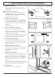
User Manual


40
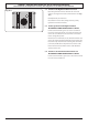
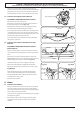
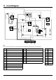
11. Circuit Diagram
P095199
2
P2
P1
1
P095199
2
P2
P1
1
a
b
e
f
c
d
1
2
b
v
P095199
2P2
P1
1
br bbbb
r
b
b
r
y
b
b
br
v
bk
bk
v
v
br
y
b
y
br
y
y
br
b
br
b
br
b
bk
b
g/y
v
y
y
or
or
g/y
r
r
bk
br
br
or
y
b
bk
bk
v
br
b
r
b
b
v
b
b
r
r
r
v
y
y
y
b
r
b
r
b
b
bbr br
br
b
b
y
br br b
br
v
or
y
E
A2
C
A1
AN
H
G1
B3
B4
B2
B1
D3
J
G2
H
F1
D1
J
D2
D4
K
J
A3
F2
F3
Key
The connections shown in the circuit diagram are for single-phase. The ratings are for 230 V 50 Hz.
Code Description
A1 Grill front switch
A2 Grill energy regulator
A3 Grill elements
B1 Left hand oven front switch
B2 Left hand oven thermostat
B3 Left hand oven fan
B4 Left hand oven fan element
C Clock
D1 Right hand oven front switch
D2 Right hand oven thermostat
Code Description
D3 Right hand oven fan
D4 Right hand oven fan element
F1 Oven light switch
G1 Left-hand oven light
G2 Right-hand oven light
H Thermal cut-out
J Neon
K Cooling fan
Code Colour
b Blue
br Brown
bk Black
or Orange
r Red
v Violet
w White
y Yellow
g/y Green/yellow
F2 Ignition switch
F3 Ignition spark generator
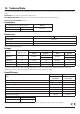
Classic, Kitchener & Professional+ 110 DF
Code Description
A1
Grill front switch
A2
Grill energy control
A3
Grill elements
B1
Left hand oven front switch
B2
Left hand oven front thermostat
B3
Left hand oven fan
B4
Left hand oven fan element
C
Clock
D1
Right hand oven front switch
D2
Right hand oven thermostat
D3
Right hand oven fan
D4
Right hand oven fan element
Key
The connections shown in the circuit diagram are for single-phase. The ratings are for 230 V 50 Hz.
Code Colour
b
Blue
br
Brown
bk
Black
or
Orange
r
Red
v
Violet
w
White
y
Yellow
g/y
Green/yellow
Code Description
F1
Oven light switch
F2
Ignition switch
F3
Ignition spark generator
G1
Left hand oven light
G2
Right hand oven light
H
Thermal
J
Neon
K
Cooling fan