
Datasheet

© 2006 Fairchild Semiconductor Corporation www.fairchildsemi.com
FSA201 Rev. 1.2.2 2
FSA201
USB2.0 Full-Speed and Audio Switches with Negative Signal Capability
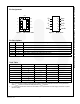
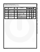
Pin Assignments
GND
Vbus
10
L
D-
D+
R
Vaudio
D+/R
ASel
D-/L
2
1
3
4
5
9
8
7
6
10
--
2
1
3
4
2
1
3
4
5
9
8
7
6
9
8
7
6
Vbus
GND
110
9
8
7
6
5
4
3
2
D+
D-
R
L
D+/R
D-/L
Vaudio
ASel
Figure 2. MicroPak™ 10-Pin Figure 3. MSOP 10-Pin
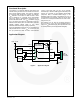
Pin Descriptions
Pin # Name
Description
1, 2 D+, D- USB data bus input sources
6 V
AUDIO
Power supply (audio)
3, 4 R, L Audio right and left input sources
9 A
SEL
Audio select to override auto USB detect when V
AUDIO
supply is present
10 V
BUS
Power supply (USB) and auto USB switch-path select
8, 7 D+/R, D-/L USB and audio common connector ports
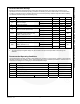
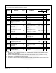
Truth Table
A
SEL
(1)
V
AUDIO
V
BUS
L, R D+, D-
LOW LOW LOW OFF OFF
LOW LOW High
(2)
OFF ON
LOW HIGH
(2)
LOW ON OFF
LOW HIGH
(2)
HIGH
(2)
OFF ON
HIGH LOW LOW OFF OFF
HIGH LOW HIGH
(2)
OFF ON
HIGH HIGH
(2)
LOW ON OFF
HIGH HIGH
(2)
HIGH
(2)
ON OFF
Notes:
1. A
SEL
- Internal resistor to GND provides auto-V
BUS
detect if there is no external connection. Forcing A
SEL
HIGH
when V
AUDIO
is present overrides the USB path even if V
BUS
is present.
2. H - Value is the threshold as defined to meet USB2.0 V
BUS
requirements and audio supply threshold in a system
(see DC Tables).