
Datasheet


FMS6501 — 12 Input / 9 Output Video Switch Matrix with Input Clamp, Input Bias Circuitry, and Output Drivers
© 2004 Fairchild Semiconductor Corporation www.fairchildsemi.com
FMS6501 Rev. 1.0.4 6
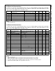
DC Electrical Characteristics
T
A
= 25°C, V
cc
= 5V, V
IN
= 1V
pp
, input bias mode, one-to-one routing, 6dB gain, all inputs AC coupled with
0.1µF, unused inputs AC-terminated through 75Ω to GND, all outputs AC coupled with 220µF into 150Ω
loads, referenced to 400kHz, unless otherwise noted.
Notes:
1. 100% tested at 25°C.
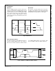
AC Electrical Characteristics
T
A
= 25°C, V
CC
= 5V, V
IN
= 1V
pp
, input bias mode, one-to-one routing, 6dB gain, all inputs AC coupled with
0.1µF, unused inputs AC-terminated through 75Ω to GND, all outputs AC coupled with 220µF into 150Ω
loads, referenced to 400kHz, unless otherwise noted.
Notes:
1. 100% tested at 25°C.
2. Adjacent input pair to adjacent output pair. Interfering input is through an open switch.
3. Adjacent input pair to adjacent output pair. Interfering input is through a closed switch.
4. Crosstalk of eight synchronous switching outputs onto single, asynchronous switching output.
5. Signal-to-Noise Ration (SNR) = 20 * log (714mV / rms noise).
Symbol Parameter Conditions Min. Typ. Max Units
I
CC
Supply Current
1
No load, all outputs enabled 80 100 mA
V
OUT
Video Output Range 2.8 V
pp
R
OFF
Off Channel Output Impedance Output disabled 3.0 kΩ
V
clamp
DC Output Level
1
Clamp mode 0.2 0.3 0.4 V
V
bias
DC Output Level
1
Bias mode 1.15 1.25 1.35 V
PSRR Power Supply Rejection Ratio All channels, DC 50 dB
Symbol Parameter Conditions Min. Typ. Max Units
AV
SD
Channel Gain
(1)
Error All Channels, All Gain Settings, DC -0.2 0 +0.2 dB
AV
STEP
Gain Step
(1)
All Channels, DC 0.9 1.0 1.1 dB
f
+1dB
1dB Peaking Bandwidth V
OUT
= 1.4V
pp
65 MHz
f
-1dB
-1dB Bandwidth V
OUT
= 1.4V
pp
90 MHz
f
C
-3dB Bandwidth V
OUT
= 1.4V
pp
115 MHz
dG Differential Gain 3.58MHz 0.1 %
dP Differential Phase 3.58MHz 0.2 deg
THD
SD
SD Output Distortion V
OUT
= 1.4V
pp
, 5MHz 0.05 %
THD
HD
HD Output Distortion V
OUT
= 1.4V
pp
, 22MHz 0.6 %
X
TALK1
Input Crosstalk 1MHz, V
OUT
= 2V
pp
(2)
-72 dB
X
TALK2
Input Crosstalk 15MHz, V
OUT
= 2V
pp
(2)
-50 dB
X
TALK3
Output Crosstalk 1MHz, V
OUT
= 2V
pp
(3)
-68 dB
X
TALK4
Output Crosstalk 15MHz, V
OUT
= 2V
pp
(3)
-61 dB
X
TALK5
Multi-Channel Crosstalk Standard Video, V
OUT
= 2V
pp
(4)
-45 dB
SNR
SD
Signal-to-Noise Ratio
(5)
NTC-7 Weighting, 4.2MHz LP,
100kHz HP
73 dB
V
NOISE
Channel Noise 400kHz to 100MHz, Input Referred 20 nV/rtHz
AMP
ON
Amplifier Recovery Time Post I
2
C Programming 300 ns