
Manual


Section
2:
Installation
Pillar and Beam Assembly, Continued
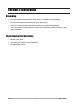
5. Place the cast iron Beam Support (#39) over the Steelyard Rod with the hook
facing to the right (when facing the scale platform).
6. Insert the Beam Cap (#45) onto the pillar rods.
•
The long side will be to the right.
7. Place Washers over the pillar rods, and then screw on the
two (2) Acorn Nuts (#44).
•
Hand-tighten only, at this time.
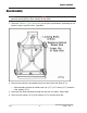
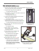
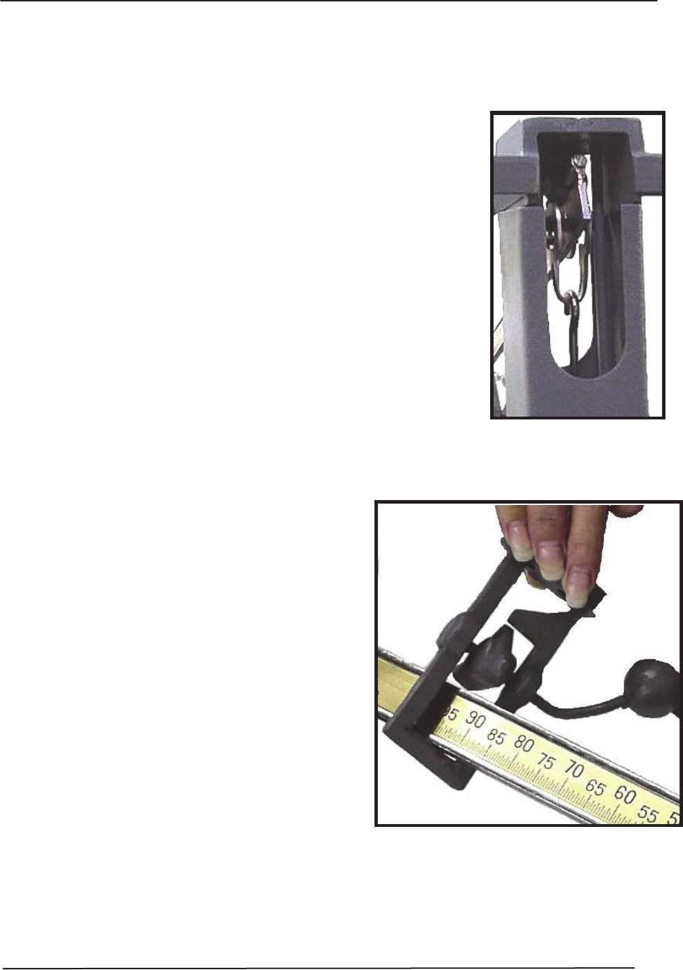
8. On the butt end on Beam
Assembly,
hook the bottom
Load Loop to the Steelyard
R
od
.
•
See image to the right.
9. Pulling the Beam up, hook the top Fulcrum Loop (of the
Beam
Assembly)
to the hook on the Beam
S
uppo
r
t
(#39).
•
The beam should hang loosely from the two hooks.
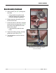
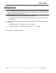
10.
Insert the Beam Lock (#43) onto the front end of the
Beam
A
ss
e
m
b
l
y
.
•
See image to the right.
Hook the bottom Load
Loop
to the Steelyard Rod.
Pulling
the Beam up, hook the
top
Fulcrum
Loop.
11.
Slide the Beam Lock (#43) over the
Beam and align it with the two (2) holes
in the Beam Cap (#45).
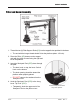
12.
Fasten the Beam Lock to the Beam
Ca
p
with the two (2) Hex Bolts (#46).
•
The handle faces the scale platform.
13.
Hang the
Counterpoise
A
ss
e
m
b
l
y
(
#54) from the Beam Tip
Loop
.
14.
Set the Sliding Poise (#52) to zero and
hand tighten the screw on its under-side.
•
Check that the beam is straight and does
not touch the sides of the
B
ea
m
Lo
ck
.
•
Shift the Cap if necessary to straighten,
and then tighten the acorn nuts securely
with an adjustable wrench.
03/13 15 50699 Rev. 4
Insert the Beam Lock onto the end of the
Beam
Assembly, then align the Beam Lock under the
two
holes in the Beam Cap. Fasten this
assembl
y
with
the two Hex
Bolts.