Instruction Manual Portable Platform Scale Models BPP1000 & BPP2000 © Copyright 1990-2013 Fancor Inc.
Portable Platform Scale Models BPP1000 & BPP2000 03/13 50699 Rev 4
© Copyright 1990-2013 This document contains proprietary information protected by copyright. All rights are reserved; no part of this manual may be reproduced, copied, translated or transmitted in any form or by any means without prior written permission of the manufacturer. Disclaimer Every effort has been made to provide complete and accurate information in this manual. However, although this manual may include a specifically identified warranty notice for the product, Fancor Inc.
Amendment Record Portable Platform Scale Models BPP1000 & BPP2000 Document 50699 Manufactured by Fancor Inc. 821 Locust St. Kansas City, MO 64106 Created 08/1990 Rev. 1 8/1990 Rev. 2 11/2006 Rev. 3 04/2012 Released Manual Updates made to include BPP2000; Revisions in text formatting, illustration updates, Descriptions, and processes Corrected parts list description Rev 4 03/2013 Misc. revisions 03/13 5 50699 Rev.
Table of Contents SECTION 1: INTRODUCTION . . . . . . . . . . . . . . . . . . . . . . . . . . . . . . . . . . . . . . . . 9 Scope of This Manual . . . . . . . . . . . . . . . . . . . . . . . . . . . . . . . . . . . . . . . . . . . . . . . . 9 Modifications . . . . . . . . . . . . . . . . . . . . . . . . . . . . . . . . . . . . . . . . . . . . . . . . . . . . . . . 9 Customer/Operator Responsibilities . . . . . . . . . . . . . . . . . . . . . . . . . . . . . . . . . . . . 9 Repair Restrictions . . . . . . .
03/13 8 50699 Rev.
Section 1: Introduction Scope of This Manual This manual provides instructions for the Portable Platform Scale Models BPP1000 and BPP2000. • Please read this manual carefully before assembling. • Untrained personnel should not attempt to make any adjustments not specified in these instructions. Modifications Absolutely NO PHYSICAL ALTERATIONS (mounting holes, etc.) are to be made to this equipment.
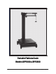
Section 1: Introduction Description The Portable Platform Scale is a compact portable unit designed for light to medium operation. It requires no external power connections and will operate in a wide variety of environmental conditions. Specifications Specifications BPP 1000 BP 2000 Capacity Division Size Platform Platform Size Overall Height Platform Height 1000 lbs. (454.5 kg) 1/2 lb. Cast iron base 21" x 23½" 42¾" About 7" Cast Iron Lever System 2000 lbs. (909 kg) 1 lb.
Section 2: Installation Unpacking • Check the packing materials for loose parts or hardware before disposal. • Check that all parts are included using the packing list. • Check for component damage that may have occurred during shipping • The scale platform under-structure arrives fully assembled, with the levers in their proper positions. Tools Required for Assembly • Needle nose pliers • Flat head and Phillips head screwdrivers • An adjustable wrench 03/13 11 50699 Rev.
Section 2: Installation Base Assembly NOTE: The following descriptions refer to “Key#” (#4, etc.) to describe parts. Use the parts list and Key# in the list to identify all such parts. 1. Place the Platform Sub Assembly on the floor upside-down, preferably on 2x4 blocks to raise it up off the floor, if possible. 2. Remove the cotter pins and washers from one side of the Axle Rod (#19). • Axle assembly includes an affixed cotter pin (#17), a 5” wheel (#16), and then a flat washer (#18). 3.
Section 2: Installation Base Assembly, Continued 5. Insert a cotter pin (#17) through the Axle Rod. • Using needle nose pliers, bend back both haves of the cotter pin to secure the wheel assembly. 6. Repeat steps two through four (2-4) for the second axle. 7. Center the axles in the base, and then insert the four locking screws (#15) into each of the tapped holes in the bottom of the base. • Located directly under the axle holes 8. Tighten the locking screws, and then secure the Lock Nuts (#14). 9.
Section 2: Installation Pillar and Beam Assembly 1. Thread the two (2) Pillar Support Rods (#1) into the tapped holes provided in the base. • The end with the longer thread should fit into the platform (about 1⁄2 inch). 2. Place the Pillar (#2) down over the support rods with the pillar cut-outs facing the right and left of the platform. 3. Insert the Steelyard Rod (#35) down through the pillar. • The bent hook on top; the loose Swivel Hook on the bottom.
Section 2: Installation Pillar and Beam Assembly, Continued 5. Place the cast iron Beam Support (#39) over the Steelyard Rod with the hook facing to the right (when facing the scale platform). 6. Insert the Beam Cap (#45) onto the pillar rods. • The long side will be to the right. 7. Place Washers over the pillar rods, and then screw on the two (2) Acorn Nuts (#44). • Hand-tighten only, at this time. 8. On the butt end on Beam Assembly, hook the bottom Load Loop to the Steelyard Rod.
Section 2: Installation Zeroing the Beam Note: Check that the weighing platform "floats" on the levers' pivots and bearings and does not bind or set to one side. The platform should return to a centered position if moved to any position then released. 1. Unlock the Beam Lock Loop to allow the beam to balance. • The beam should move up and down freely coming to rest in the center of the trig lock opening. 2. Balance the beam by adjusting the balance ball at the butt end of the beam, using a screwdriver.
Section 2: Installation Troubleshooting If the beam will not balance using the balance ball, check the following: • Is the poise is at 0 (zero), and is the poise screw is snug? • Is the platform free and “floating”? • Is the beam load rod connected properly on both ends? • Is something under the platform inhibiting the levers (floor debris)? • Are there any weights on the counterpoise hanger, and is it on the Tip Loop? • Is the beam hanging from the middle loop? • Is the Beam Lock Loop (#43) o
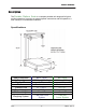
Section 3: Parts Parts List Key # BPP1000 Part # BPP2000 Part # 55017 1 2 3 4 5 6 7 8 9 10 11 12 13 11, 12, 13 14 15 16 17 18 19 24 25 26 27 28 29 30 31 32 33 34 35 71622 58933 95847 95848 95855 58937 95856 95857 95858 95859 71623 71624 71625 58938 95867 95868 95869 71628 71629 71630 95861 72948 58939 BPP1000 Series, 24" x 21", 1K x .
Section 3: Parts Parts List, Continued Key # 36, 37, 38 37 38 39 40 40, 41, 42 41 42 43 44 45 46 47 48 47, 48, 49 BPP1000 Part # BPP2000 Part # Description 71594 95839 71591 71595 95840 71592 95841 71593 77229* 77227* 95843 55017 71633* 75711* 50 51 51, 52, 53 53 54, 58, 59, 60 55, 56, 57 55, 56, 57 55 56 57 58 59 60 61 62 N/S N/S 71632 95842 58935 71598* 74392* 58936 95853 95854 95865 95866 71586 71587 Loop Assembly Cotter Pin Bearing Support Beam Loop Loop Assembly Cotter Pin Bearing Lock As
Section 3: Parts Parts Diagram 46 43 45 44 39 40 52 55 56 57 49 54 1 3 61 2 62 33 6 25 31 26 35 8 7 9 5 10 11 12 13 14 17 15 24 34 18 16 19 4 03/13 20 50699 Rev.
Portable Platform Scale Models BPP1000 & BPP2000 Document 50699