Installation Manual 2000 SERIES Rocker Column Railroad Scale © 2001-2010 by Fairbanks Scales Inc.
Amendment Record 2000 Series Rocker Column Railroad Scale 50614 Manufactured by Fairbanks Scales Inc. 821 Locust Kansas City, Missouri 64106 Created 5/01 Issue #1 5/01 New Product Issue #2 5/02 Update Part Numbers Issue #3 6/02 Update Specifications Issue #4 10/03 Updated entire Manual Revision 5 03/10 Updated entire manual per engineering and ECO 636. Disclaimer Every effort has been made to provide complete and accurate information in this manual.
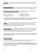
Table of Contents Section 1: Introduction 1-A: 1-B: 1-C: 1-D: 1-E: 1-F: 1-G: 1-H: Introduction & General Description Specifications Rails & Anti-Creep Devices Regulations; Excerpts from the AAR Scale Handbook Foundation Construction & Installation Grout Plates Rocker Column Loadcells Ground Rods Page Page Page Page Page Page Page Page 5 6 7 8 11 11 11 11 Page Page Page Page Page Page Page Page Page Page Page Page Page Page Page Page 13 13 14 14 15 16 18 19 20 21 23 23 25 26 28 30 Section 2: Installati
Index of Illustrations: 50614-1 50614-2 50614-3 50614-4 50614-5 50614-6 50614-7 50614-8 50614-9 50614-10 50614-11 50614-12 50614-13 50614-14 50614-15 50614-16 50614-17 50614-18 50614-19 50614-20 50614-21 50614-22 50614-23 50614-24 50614-25 50614-26 50614-27 50614-28 50614-29 50614-30 50614-31 50614-32 50614-33 50614-34 50614-35 03/10 Single module end view Side view Different wheelbase lengths Component identification Anti-creep device Suggested anti-creep installation Rail miter gap Ground rods, Single -
A.A.R. Combination Railroad Track / MTS Scale NOTE: This manual is intended to compliment and be used in conjunction with the Certified Prints provided by FAIRBANKS SCALES. Installation should be attempted only with the presence and guidance of experienced personnel who are fully familiar with the assembly of these scales. Please read this Bulletin in its entirety BEFORE setting scale hardware.
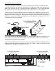
1 2 50614_2 1: A single consists of one 12' 6" long pre-assembled module. 2: A double consists of two 12' 6" long modules that are configured to assemble together. The double is supported by three sections, and is 25' long. 50614_3 Both the combination and placement of the scale modules will accommodate rail cars with different wheelbase lengths. A single 12' 6" Module weighs 5000 lbs, and has a Sectional Capacity of 85 Tons.
1-C: Rails & Anti-Creep Devices The Scale is designed to accept a 115 lb. rail with Foster #62 rail clip. The approach rails and Scale Weigh Rail should be the same weight. The approach anchor bolts, approach rail plates, rails, rail clips, and anti - creep devices are all optional items. They can be supplied by Fairbanks Scales when ordered as accessories, otherwise they are not supplied.
Rails should be miter cut at the ends of the weighrails and approach rails to assure a smooth transfer of wheels in order to reduce impact loading to the scale. 3/8 inch gap 1 2 45 50614_7 1-D: Regulations: This Scale is designed and manufactured in accordance with regulations established by Handbook 44 as adopted by the National Conference of Weights and Measures (NCWM), the American Association of Railroads (AAR), and the National Institute of Standards and Technology (NIST).
Ventilation: All scale pits shall be ventilated to meet the needs of each particular case to minimize the relative humidity in the pit and to retard corrosion of scale parts and structural steel. Entrance to the Scale Pit: Suitable access to the Scale pit shall be provided. The entrance shall be closed by a suitable closure fastened to prevent the entry of unauthorized persons.
Power Source The power source of the electronic instrumentation and load cell circuitry shall conform to the following: Voltage - 115 v AC +/- 10 v Frequency - 60 Hz, +/- 0.25 Hz The power source must be reasonably free from harmonics and electrical transients. Fusing shall be provided at 15 amp unless otherwise specified by the manufacturer. The power source shall be a separate circuit back to the distribution transformer. One side of the 115 v power source shall be at a ground potential.
1-E: Foundation Construction & Installation Use only certified prints that are marked for the particular installation, customer, and scale. All the dimensions indicated on the certified prints must be rigidly and faithfully followed during all phases of construction. There is very little tolerance for misplacements and mistakes.
The following drawing shows correct placement of ground rods.
Section 2: Installation: 2-A: General Service Policy Prior to installation, it must be verified that the equipment will satisfy the customer's requirements as supplied, and as described in this manual. If the equipment cannot satisfy the application and the application cannot be modified to meet the design parameters of the equipment, the installation should not be attempted. Overview: 1.
5. Has the service technician thoroughly reviewed the installation procedures? 6. Has the service technician reviewed the recommended setup with the Area Sales Manager or Area Service Manager, and identified all necessary variations to satisfy the customer's particular application? 2-C: Unpacking: 1. Check that all components and accessories are on hand, and agree with the customer's order. 2.
2-E: Recommended Installation Sequence: After pit is completed, follow this sequence: Measure pit squareness, depth, width, and length against certified prints Measure cast-in anchors, pier elevation on all piers against certified prints Dimensions MUST be correct before installing scale hardware Using packing list, be sure all scale elements/parts have arrived intact and Undamaged Then install: Grout plates Checking brackets Scale modules and associated hardware Loadcells, Bearings, and associated hardw
2-F: Foundation Construction & Installation Form(s) Tied Rebar Supports 50614_11 Above: Preparing forms for the slab, upon which the 2000 Series Rail Module(s) will be installed. Use only certified prints that are marked for the particular installation, customer, and scale. All the dimensions indicated on the certified prints must be rigidly and faithfully followed during all phases of construction. There is very little tolerance for misplacements and mistakes.
Check Post 4X4 Lag Screws 50614_13 Check Posts limit the platform movement, and also serve as a safety pier. They are designed to be embedded in the poured slab / foundation. Check Posts weigh approximately 70 pounds. After building, supporting, and securing the main forms, the Check Posts are securely fastened to 4 X 4 with Lag screws. They are then placed and secured into position as shown. For exact dimensions, refer to the CERTIFIED PRINT.
2-G: Foundation Inspection Excerpts from Fairbanks Scales form FF-2267; Foundation Field Check list A Foundation Inspection should ALWAYS be performed prior to Scale installation, to confirm the Foundation is constructed correctly and is ready for installation. If possible, this should be done prior to the scale shipment. TOOLS REQUIRED: Certified drawings and site plan.
2-H: Foundation Inspection Check list 3: 50614_15 2: 1: Length & Width Check 4: A B Measurement A to A=________ Diagonal Measurements Check B A Measurement B to B=________ Strings Side View Pier Height Check Pier Pier 1 3 5 7 9 2 4 6 8 10 Loadcell Center Line A C C B A B CL C C Loadcell Center Line A = Coping length B = 1/2 of the coping length, or Centerline C = Distance from Centerline to load cell Center lines 03/10 19 = Concrete Nails CL = Centerline of Scale 50614 Re
2-I: Grout plate assemblies: Caution: Base plates weigh approximately 180 lb.. apiece. Work Safely. Grout Plates 50614_16 1: Clean the top of the piers thoroughly, and ensure they are free of any oil or grease deposits. Clean the threads of all base plate pier bolts with a wire brush, using a thread file to restore any damaged threads. Lightly oil the threads, and ensure the threads are clean and in good condition by running a threaded nut down and up the threads of the bolt.
Three (3) Leveling Screws on 1/4" flat steel plates per Grout Plate Pier Bolts Grout Plate Grout Plate 1 1/2" Min Front View Side View 50614_18 4: Insert greased leveling screws into the provided tapped holes in the Grout Plates, and place a cut piece of 1/4" Flat Steel under each leveling screw. Adjust each screw to raise the plate off of the blocking a minimum of 1 1/2", and to approximately level the plate. Remove the blocking from underneath the Grout Plate.
Bolted Shims Welded Bumper Slotted Holes LATERAL CHECKING LONGITUDINAL CHECKING Adjust here Adjust here 50614_20 Embedded Check Post The Check Brackets are designed to limit and restrict the Scale Modules movement for 360 degrees. When they are properly adjusted, they will limit any movement from a minimum of 1/16" to a maximum of 1/8". Each Check Bracket is provided with slotted mounting holes that are three (3) inches long.
50614_22 Mason Line CENTER 8: Set up a mason line to check and ensure that the centers of the main beams are centered on the approach anchors in the concrete approaches for the entire section. Ensure that the scale module(s) are centered both laterally and longitudinally on the foundation and approaches. 9: When the weighbridge is properly positioned and centered, bolt the check brackets to the Weighbridge.
3/4-10 X 3 1/2" Hex Bolt Upper Receiver Plate & Bearing Load cell 3/4-10 X 3" Hex Bolt Clamp Plate Lower Receiver Plate w Bearing Load cell 1 1/2" Min 50614_24 Front View Side View Tighten Upper Bolts Shift Clamp Plate to Plumb & Level the Loadcells Load cell Load cell 1 1/2" Min Front View Side View 50614_25 11: Beginning with an end Section, position a suitable capacity jack to raise and lower the module corner as needed. Install and tighten the upper receiver plate to its final torque value.
Side View LEVEL Load Cell LEVEL 1 1/2" Min 50614_26 12: Plumb the load cells by lifting the weighbridge up slightly and shifting the load cell base plate on the grout plate. Use a machinists level to align and ensure a plumb and level condition. 13: When loadcell is plumb and level, tighten the lower receiver plate bolts to their final torque value. Repeat for all loadcells in the scale.
Maintain same elevation 50614_28 Baseplate Leveling Screws 15: Double module installations contain a middle section. For the middle sections, the elevation reference is both the absolute level of the main beams with respect to the end sections, and the equal loading of the loadcells that support the middle of the scale. Adjust the grout plate leveling screws to level the modules. Alternately, a transit can be used to compare and maintain elevation, and a tightly stretched mason line.
2 1 4 3 50614_30 Single modules are supported by two sections, or four load cells. A final grout plate elevation adjustment should be made to match the mV/V outputs of the load cells to assure correct distribution of the scale's deadload among the four (4) points of support. Adjust the grout plate leveling screws (equally) to match loadcells 1, 2, 3, and 4. When this has been completed, ensure each loadcell grout plate is level to within .015" per foot.
2-J: Grouting the Grout plates: Grout becomes the base which supports the entire structure. Grout MUST be fully supporting the grout plates with NO gaps or spaces. A good method is to build the forms slightly bigger than the plate to permit the pouring and the rising of the grout mixture. The pier should be thoroughly saturated with clean water for a minimum of 4 hours.
• Pour the grout mix from one end until it fully reaches the other side and rises to fill the form completely. By using this method, there will be no gaps or air pockets. Vibrators are not recommended due to the danger of disturbing the placement of the loadcell base plate(s). Ensure the grout mixture totally fills all voids. Trim grout at an angle for the entire grout base Grout Concrete Pier 50614_32 • The A.A.R.
2-K: Grounding #1, #3, & #5 round G Rods mustconnect to both rails #6 #1 #7 #3 Scale 1 #2 Scale 2 #4 #8 #5 = Ground Rod Conduit between Modules Conduit to Instrument 50614_33 A 1: Clean all ground rod end(s) with abrasive to assure a good electrical connection. Keep all ground straps untwisted, clear of standing water, with a drip loop, and as short as possible. Secure the strap to the ground rods with the provided clamp and coat with grease.
Section 3: Maintenance Inspect the Scale and its understructure on a regular basis to ensure: 1: The approach rails and Scale rails remain securely in position and are properly fastened in place. 2: The space between the deck edge, pit coping, and rails is clear and free of material which could jam the deck and cause inaccurate weights. 3: The Scale Foundation and understructure is clean and dry. Keep the foundation and the understructure of the Scale as clean and as dry as possible.
Section 4: Parts List End Section Center Section 50614_34 Single Module 03/10 32 50614 Rev.
Item No. Part No.
Parts Not Pictured: Part# Description Qty 59600 59795 54591 Cut ¼" Steel Plates (2" X 2" Square) 5/8-11 X 4" Chk Stand Leveling Screw ¾-10 X 6" Base Plate Leveling Screw Weighbridge Assembly Bolts 54532 54229 54199 54217 54402 ¾-10 X 3" Hex Bolt ¾-10 X 3 ½" Hex Bolt A325 with Nut ¾ -10 X 2 ¼" Hex Bolt with Nut.
Appendix I: Recommended Tools & Equipment: Local RailRoad Approval Certified Prints Service manuals for ALL equipment being installed. Lifting Device capable of safely lifting 5000 lbs or more Laser or Contractor's level (Transit) Hand Tools Mason Line 25 Foot tape measure 100 Foot tape measure Precision Level (Starrette Model 98 Mechanics Level, 6 inch long model) Torque wrench of suitable capacity Thread file; Standard thread sizes of 10, 8, 7, 6.
Appendix III: Materials: Grout shall be precision, packaged dry, non-metallic, hydraulic, non-shrink, and non-gaseous. Grout shall meet or exceed ASTM C-1107 and Corps of Engineers CRD-C621. Grout shall be bleed free and attain a minimum of 8000 psi compressive strength in 28 days at flowable consistency. Grout MUST be mixed to a flowable consistency as specified by the grout manufacturer. " Quantity required will vary according to pier heights.
Appendix V: Tolerances: Load Cell Grout Plates, level within 0.015" per Foot Appendix VI: Loadcell Specifications: Type: COC Safe Load Limit: Capacity: Height: Input Resistance: Output Resistance: Insulation Resistance: Calibration: Cable Length: LCF-HR4020-4A #97078 / Class III L, Single: 10,000 d 150% of Rated Capacity. 110,000 LB. 7" 1150 ohms 1000 ohms 10 giga ohms (1000 meg ohms) 2 mV/V 15 feet Minimum Verification Intervals (V MIN): Wiring: 50K lb: 100K lb: 200K lb: 1.5 lb 3.0 lb 6.
APPENDIX VIII: Concrete & Slump Testing: Concrete is produced from the mixing of sand (fine aggregate), stone (coarse aggregate), cement and water. The water combines with the cement to form a fluid paste often referred to as "plastic". The paste is combined with the sand and stone to make a workable "plastic" concrete that can be poured, shaped, smoothed, and molded. The plastic concrete then hardens around the sand and stone forming a solid mass.
The slump test is a direct measure of the amount of water in the mixture, unless ADMIXTURES are added. Admixtures are liquid chemicals added to concrete to make it easier to place without the reduction in strength adding water would cause.
APPENDIX X: 2000 Series J-Box Bracket Accessory This accessory provides a means to mount the smart sectional controllers, pit power supplies, and analog junction boxes away from the scale frame. Each bracket can accommodate a maximum of two boxes. The illustration below shows a typical installation of these brackets. The part number of the bracket is 106314. 50614-35 03/10 40 50614 Rev.
2000 Series Railroad Track Scale Manufactured by Fairbanks Scale, Inc. 821 Locust Kansas City, MO 64106 www.fairbanks.