Installation Manual A.A.R. Combination Railroad Track / MTS Scale Model(s): 12-1492 12-1493 12-1494 12-1495 12-1496 © 1999-2012 by Fairbanks Scales Inc.
Amendment Record A. A.R. Railroad Combination MTS Scale Model(s): 12-1492,12-1493,12-1494,12-1495 50538 Manufactured by Fairbanks Scales Inc. 821 Locust Kansas City, Missouri 64106 04/12 Created 9/99 Issue #1 9/99 Software Update. Issue #2 12/01 Update arrangement/flow.
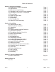
Table of Contents Section 1: General Information 1-A: Introduction & General Description 1-B: Specifications 1-C: Rails & Anti-Creep Devices 1-D: Regulations from the AAR Scale Handbook 1-E: Foundation Construction & Installation 1-F: Ground Rods 1-G: Load Cell Base Plates 1-H: Check Stands 1-I: Weighbridge 1-J: Deck Construction 1-K: Load Cell Flexure Assembly Page Page Page Page Page Page Page Page Page Page Page 9 9 10 11 13 14 14 15 15 15 16 Section 2: Installation 2-A: General Service Policy 2-B: Pr
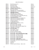
Table of Contents, Continued Appendix I: Recommended Tools & Equipment Page 54 Appendix II: Required at Jobsite Page 55 Appendix III: Materials Page 55 Appendix IV: Torque Values Chart Page 56 Appendix V: Tolerances Page 56 Appendix VI: Load Cell Specifications Page 56 Appendix VII: Concrete & Sump Testing Page 57 Appendix VIII: About the AAR, AREMA, & AREA Page 58 Appendix X: Special Product Applications -Short Load Cell Assembly Page 59 04/12 6 50538 Rev.
Index of Illustrations: 50538-1 50538-2 50538-3 50538-4 50538-5 50538-3A 50538-6 50538-7 50538-7A 50538-7B 50538-8 50538-9 50538-10 50538-11 50538-12 50538-13 50538-14A 50538-15 50538-16 50538-17 50538-18 50538-19A 50538-20 50538-21 50538-22 50538-23 50538-24 50538-25A 50538-26 50538-27 50538-28 50538-29 50538-30 50538-31 50538-32 50538-33 50538-34 50538-35 50538-36 50538-37 50538-38 50538-39 50538-40 50538-41 50538-42 50538-14 04/12 Deck with recessed rail Anti-Creep Device Rail Miter Cut Gaps Ground Rod
A.A.R. Combination Railroad Track / MTS Scale NOTE: This manual is intended to compliment and be used in conjunction with the Certified Prints provided by FAIRBANKS SCALES. Installation should be attempted only with the presence and guidance of experienced personnel who are fully familiar with the assembly of these scales. Please read this Bulletin in its entirety BEFORE setting scale hardware. SECTION 1-A: Introduction & General Description: The Fairbanks Model A.A.R.
1-C: Rails & Anti-Creep Devices The Scale is designed to accept a 115 lb. rail with Foster #62 rail clip. The approach rails and Scale Weigh Rail should be the same weight. The approach anchor bolts, approach rail plates, rail clips, and anti - creep devices are all optional items. They can be supplied by Fairbanks Scales when ordered as accessories, otherwise they are not supplied.
1-D: Regulations: This Scale is designed and manufactured in accordance with regulations established by Handbook 44 as adopted by the National Conference of Weights and Measures (NCWM), the Association of American Railroads (AAR), and the National Institute of Standards and Technology (NIST).
Bearing Pressures Under Foundations: The bearing areas of the foundation footings shall be such that the pressure under the footings will not exceed: For fine sand and clay .................................. 4,000 lb. per square foot For coarse sand or hard clay ....................... 6,000 LB per square foot For boulders or solid rock ...........................
Cabling: All cabling between loadcells, junction boxes, and electronic instrumentation shall conform to the following: All cable shields shall be interconnected and carried to a single ground. This should be a separate ground from the power source ground and be provided for the loadcells and instrumentation circuits only. It should be a copper rod which, when possible, is driven to the depth of the water table.
1-F: Ground Rods: Ground rods are essential in providing protection to the electronic components and loadcells from both lightning surges and static discharges. Pit ground rods shall be tied to the foundations steel reinforcement rod (rebar) prior to pouring, and shall protrude 4 inches above the pit floor. Ground rods for approach rails shall be installed in the approach rail cut-outs and tied to the rebar assembly.
1-H: Check Stands: Check rods allow for vertical movement in order to transfer weight force to the load cells but they do not allow for lateral or side movement. Checking stands must be level and on the same plane. All check rods must be level within 1/100” per foot when weighbridge is at correct elevation. Grouting the check stands MUST NOT take place until the load cell base plates are adjusted to their final height.
1-K: Load Cell Flexure Assembly: The Load cell flexure assemblies maintain the load cells in a vertical position. In application, the design uses a 200,000 lb capacity compression load cell mounted in a support assembly. The support assembly contains an upper flexure assembly protected by a wear plate, and weight(s) applied to the scale are transferred to them from the top bearing plate assembly.
Section 2: Installation: 2-A: General Service Policy Prior to installation, it must be verified that the equipment will satisfy the customer's requirements as supplied, and as described in this manual. If the equipment cannot satisfy the application and the application cannot be modified to meet the design parameters of the equipment, the installation should not be attempted. Overview: 1.
5. Has the service technician thoroughly reviewed the installation procedures? 6. Has the service technician reviewed the recommended setup with the Area Sales Manager or Area Service Manager, and identified all necessary variations to satisfy the customer's particular application? 2-C: Unpacking: 1. Check that all components and accessories are on hand, and agree with the customer's order. 2.
2-E: Recommended Installation Sequence: After pit is completed, follow this sequence: Measure pit squareness, depth, width, and length against certified prints Measure cast-in anchors, pier elevation on all piers against certified prints Dimensions MUST be correct before installing scale hardware Using packing list, be sure all scale elements/parts have arrived intact and Undamaged Then install: Base Plate Assemblies Check Stands Wood blocking and cribbing Weighbridge Steel Weighbridge Sections Load Cell F
2-F: Foundation Inspection Excerpts from Fairbanks Scales form FF-2267; Foundation Field Check list A Foundation Inspection should ALWAYS be performed prior to Scale installation, to confirm the Foundation is constructed correctly and is ready for installation. If possible, this should be done prior to the scale shipment. TOOLS REQUIRED: Certified drawings and site plan.
2-G: Foundation Inspection Check list 50538-3A 3: 2: 1: Length & Width Check 4: A B Measurement A to A=________ Diagonal Measurements Check B A Measurement B to B=________ Strings Side View Pier Height Check Pier Pier 1 3 5 7 9 2 4 6 8 10 Loadcell Center Line A C C B A B CL C C Loadcell Center Line A = Coping length B = 1/2 of the coping length, or Centerline C = Distance from Centerline to load cell Center lines 04/12 21 = Concrete Nails CL = Centerline of Scale 50538 Re
2-H: Base plate assemblies: Caution: Base plates weigh approximately 245 lb.each. Work Safely. 1: Clean the top of the piers thoroughly, and ensure they are free of any oil or grease deposits. Clean the threads of all base plate pier bolts with a wire brush, using a thread file to restore any damaged threads. Lightly grease the threads, and ensure the threads are clean and in good condition by running a threaded nut down and up the full threads of the bolt. Remove all nuts from the pier bolts.
2-J: Weighbridge Steel: Caution: Individual Steel beams can weigh as much as 5,500 lb. each. Work Safely. Assembling in Sections: It is recommended to assemble the weighbridge in 3 sections near the pit, with each section located near its intended installation location. The means to safely move and position the various steel beams will be required to facilitate the assembling of the weighbridge.
2-K: Weighbridge Hardware 50538-7B 4 5 4 1 3 2 1 Loadcell Top Bearing Plate Weighbridge Check Bracket 1: Part # 54532; 3/4-10 X 3" Hex Bolt. Qty 32 required to connect the load Cell Top Bearing Plate Assy's to Main Beam bottom flange. Their final Torque value is 150 foot pounds. Note: The Load Cell Top Bearing Plate Assy mounting holes are tapped 3/4-10. 2: Part # 54229; 3/4-10 X 3 1/2" Hex Bolt A325 with Nut.
2-L: Assembling Weighbridge Sections 1: Identify each main beam pair per the certified prints, and select the appropriate end section beams as the first to begin assembling. Place one main beam onto blocking, ensuring it is supported and stable.
4: Install the stiffener plate and the top bearing plate assemblies. The mounting bolts will install into the Top Bearing Plates threaded holes. Do not tighten to their final torque value at this time. Do not perform any welding to the end sections at this time. Hex Bolts Main beam Flat Washers Stiffener Plate Top Bearing Plate Assy 50538-11 5: In similar manner, assemble the center section (s), and the other end section. 04/12 26 50538 Rev.
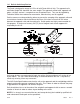
2-M: Installing Weighbridge Sections Caution: Weighbridge Sections can weigh as much as 17,000 lb. each. Work Safely. 1: Place wooden blocking and cribbing material suitable for supporting and jacking the weighbridge steel into position near each pier and base plate. Each section will require four points of support, therefore arrange the placement of these supports accordingly.
50538-13 ABOVE: Check weighbridge steel for squareness by suspending a plumb bob at the juncture of the previously established "centering" line, and at the juncture of the middle web of the main beams. Measure and observe the distance between the plumb bob line and the web, it should be the same at the top and bottom. 4: When end section has been centered, install the middle section, and connect the sections together as indicated on the certified drawings.
2-N: Load Cell Flexure Assembly: 04/12 29 50538 Rev.
End Center 50538-15 Referring to the detail above, note that the "open" side of the assemblies at end sections face the center of the scale; middle sections have assemblies installed with the "open" side facing the end of the scale. TIP: For Analog Instrumentation, measure the bridge resistance of each load cell, and pair the closest matches for installation in each section. Lower Assembly: 1: Ensure the base plate is clean and free from any dirt and debris.
Upper Assembly: 1: Place the upper button bearing assembly to the underside of the upper flexure assembly. With the wear plate correctly orientated as to its corner countersunk holes, apply grease and install the four ¼-20 x ½” flat-head screws through the wear plate, flexure assembly, and into the bearing assembly.
Pit coping 50538-17 Level Approach Deck coping Main Beam Main Beam 2: For the end sections, the elevation reference is the end wall (approach) pit coping. Place and clamp deck coping across the main beams at an end section facing the pit wall coping. Adjust the load cell base plate leveling screws of both base plates in the end section to level the approach as shown above. Ensure both base plates are also level to within 1/64” per foot. 3: Proceed to the next section, which is a middle section.
2-P: Leveling Load Cell Flexure Assemblies: Main Beam ener Plate Top Bearing Plate Upper Flexure LEVEL B A Top Bearing Plate LEVEL Load Cell LEVEL Upper Flexure Load Cell LEVEL Base Plate 50538-19A Base Plate 1: Starting at one end section, lift the main beam slightly from one load cell at a time and loosen the three screws that secure the flexure to the support assembly block, and note any space between the flexure and the block.
Top View of Scale 1 3 5 7 2 4 6 8 Loadcell's Conduit 50538-20 This final base plate elevation adjustment should be made to match the mV/V outputs of the load cells to assure correct distribution of the scale's deadload among the eight (8) points of support. Adjust the base plate leveling screws (equally) to match loadcells 3, 4, 5, and 6. Then adjust to match loadcells 1, 2, 7, and 8. When this has been completed, ensure each load cell base plate is level to within 1/64” per foot.
7: Insulate and separate each load cell's wiring from adjoining wires and from the steel with insulated electrical tape. Be certain load cell cables are isolated from contact with steel and not attached to any junction boxes. Be certain load cell cables are isolated from contact with steel and not attached to junction boxes. Welding ground should be kept as close to the electrode (welding rod) end as is practical.
2-Q: Grouting Load Cell Baseplates: Grout becomes the base which supports the entire structure. Grout MUST be fully supporting the stands and plates with NO gaps or spaces. A good method is to build the forms slightly bigger than the stand to permit the pouring and the rising of the grout mixture. The pier should be thoroughly saturated with clean water for a minimum of 4 hours.
3" Min. 3" Min. Forms (Typ.) Forms (Typ.) Grout 1.0" Min. Concrete Pier 50538-21 3. Forming: • Forming must be completed and installed before starting to pour grout. • Forms shall be slightly larger (six to seven inches) than the dimension of the load cell base plate or checking stand. • Forms shall be of sufficient strength, anchored properly, and sealed. Seal with caulk and use a form release agent on forms if required. Leave access for pouring grout in a convenient place. 4.
50538-22 TIP: Forms can sometimes be easily made and secured to the pier as shown above. Be careful not to tighten the pier nuts too tightly on the wooden forms. DO NOT DISTURB THE LOAD CELL BASE PLATE'S LEVEL, ELEVATION, OR LOCATION IN ANYWAY !!! Trim grout at an angle for the entire loadcell baseplate Base Grout 50538-23 Concrete Pier • The A.A.R.
2-R: Check Rods: 1: Check rods allow for vertical movement in order to transfer weight force to the load cells but they do not allow for lateral or side movement. Prepare the check rods, special convex / concave washer sets, and hardware for installation. Clean the threads with a wire brush, using a thread file to restore any damaged threads. Lightly grease the threads, and ensure the threads are clean and in good condition by running a threaded nut up and down the full threads of the checkrods.
TOP VIEW 1 3/8" Hole 1 5/8" Hole 5/8-11 Tapped Hole for Leveling Screw 50538-26 TOP VIEW 1 5/8" Hole 1 3/8" Hole 5/8-11 Tapped Hole for Leveling Screw LEVEL CHECKROD 50538-27 2: Install the check rod into position, and place the rest of the hardware onto both ends, leaving the hardware loose. All check rods must be level within 1/100" per foot when weighbridge is at correct elevation. Raise or lower the Pier Checking stand with its leveling screws until this is achieved. 04/12 40 50538 Rev.
2-S: Check Rod Adjustment: NOTE: See Section 2-Q for complete assembly descriptions of Grouting Check Stands, Grout Selection, Surface Preparation, Forming, and Mixing and Pouring. NO LATERAL MOVEMENT *NOTE 50538-28 All checkrod threads and Spherical washer sets shall be greased. * NOTE: All checkrods shall be adjusted so there is no lateral movement at all, while the checkrod can be rotated to ensure the scale is not being subjected to any side forces or influence from them.
2-T: Deck Forming: 4 3 1 Above: 1: Deck Coping 2 50538-29 2: Manhole access 3: Poured concrete 4: Rail pocket Deck forming will prepare a custom fitted deck that provides correct clearance while conforming to the pit walls and rails. The construction of the deck provides several custom "pans" to contain the reinforcement rods, manholes, and to support the poured redi-mix concrete until it cures. Weld Deck Coping Hex Nut Rock Guard Weld 50538-30 Rev.
Weld Pit Coping 2X4 LEVEL Main Beam Nut Outrigger 50538-31 Rev. 2 2: The deck channel is then placed into position. A 2 X 4 can be used as shown to help force and position the deck channel against the pit wall. Ensure the deck channel is level with the pit coping, then weld the nut to the pit coping as shown. LEVEL LEVEL Maintain Clearence Weld Shim here with plate steel if req. Outrigger 50538-32 Rev. 2 \ 3: Pit coping irregularities may cause gaps between the deck coping and outriggers.
Weld 50538-34 Rev. 2 4: Layout the deck coping on the main beams beside each rail as shown. Position the deck coping to provide rail clearances per the certified prints. Ensure they are straight. Clamp and weld the deck coping as shown. Welds should be one (1) inch long, and at sixteen (16) inch intervals more if required.
Weld additional support between crossmembers as needed 50538-36 Rev. 2 7: Additional supports are required (between the crossmembers and outriggers) to prevent the corrugation from collapsing when the redi-mix concrete is poured and floated. This support can be provided by welding flat steel plate or reinforcement rod as shown. 8: Install the manholes exactly as noted in the certified prints. Ensure they are placed in their correct positions on the corrugation, and are supported properly.
Fill the Rail Pockets with Mastic or Cold Patch 50538-38 Rev. 2 11: After the concrete has cured and the rail is installed, fill the rail pockets continuously with bituminous mastic or asphalt, except at the ends of the scale where clearance must be maintained between the approach and scale rail, and between the pit coping and scale deck coping. 6 1/2" 1 1/4" 6.0" 6" X 1/4" Plate 6 1/2" Long 8 ea.
2-U: Junction Box(s) The A.A.R. Combination Railroad Track / MTS Scale is shipped for installation to a 2500 Series Instrument. As part of that installation, there may be five (5) junction boxes to be installed in the pit. To provide mounting for these junction boxes, locate the following part that is shipped with the scale. Part # QTY Description 55766 5 Bar, Junction Box; 3/4" X 1 1/4" (2 holes tapped 3/8-16). The Junction Box bars can be welded to cross member at each load cell section.
2: Connections to the weighbridge are installed by drilling a hole in the welded flange (stiffener). Scrape / sand enough paint / coating away to make a good electrical connection and secure with the provided hardware. 3: Connect the strap to the weighbridge steel using the provided set screw terminals and coat with grease AFTER the connection has been made. 4: Ground rod #3 should be located near the interface conduit.
Section 3: Service & Maintenance 3-A: Basic Maintenance: Inspect the Scale and its understructure on a regular basis to ensure: 1: The approach rails and Scale rails remain securely in position and are properly aligned and fastened in place. 2: The space between the deck edge, pit coping, and rails is clear and free of material which could jam the deck and cause inaccurate weights. 3: The Scale Pit and understructure is clean and dry.
Section 4: Parts List 04/12 50 50538 Rev.
-Section 4: Parts List, Continued FE AAR Track Scales Load Cell Assembly Parts and Hardware Parts Part No. Part Description Int Sect, Upper Bearing Plate (8 holes) 1 Shown in diagram. 61293 End Sect. Upper Bearing Plate (4 holes) 1 " 58652 12125 58650 12126 12127 12122 58782 81352 145865 Top Bearing Plate (w/ Teflon Pad) Wear Plate Upper Flexure Assy Clamp Bar 0.05" Upper Flex Assy Shim 0.
FE AAR Track Scales, Continued Weighbride Assembly Parts and Hardware Hd Parts Part No. Part Description Qty and Location Notes 61037 Girder Conn. Plate, 1/2" x 8" x 2', 16 Holes 2 per interior section beam splices (one each side of web) 61295 Dam Plate 2 per open trough to dam mastic. 61153 Angle Brace, L3" x 3" x 1/2", 5' Lg.
Grounding Kit Components 60811 65061 11296 58618 54569 54757 54368 66942 66978 54054 50584 ¾" X 8' Ground Rod, Copper Plated, 1/2-1, Ground Clamp Braid Shield, 5/8" ID - #8 AWG Ground Rod Cap, PVC 1/4-20 X 1 ½" Hex Cap Screw 1/4" Spring Lock Washer 1/4-20 Hex Nut Connector Clamp I Beam Clamp 1/4-20 x 1/2” Cap Screw Manual Grounding Kit Items below are replaced components from the previous Grounding Kit.
Appendix I: Recommended Tools & Equipment: QTY 2 EA 1 EA 1 EA 1 EA 1 EA 1 EA. 1 EA 1 EA 1 EA 1 EA 1 EA 4 EA 2 EA DESCRIPTION MASON LINE 25 FOOT TAPE MEASURE 100 FOOT TAPE MEASURE TRANSIT PRECISION LEVEL (Starrette Model 98 Mechanics Level, 6 inch long model) TORQUE WRENCH OF SUITABLE CAPACITY THREAD FILE; STANDARD THREAD SIZES OF 10, 8, 7, 6.
Appendix II: Required at the Jobsite: 117 VAC Electric Power (Extension cords as needed) Water Suitable crane(s) Rigging (I.E. Straps, 4 leg drops, etc.) NOTE: The weight capacity of all lifting and rigging equipment must be suitable for their intended use. Appendix III: Materials: Grout shall be precision, packaged dry, non-metallic, hydraulic, non-shrink, and non-gaseous. Grout shall meet or exceed ASTM C-1107 and Corps of Engineers CRD-C621.
Appendix IV: Torque Values Chart All Values are Pounds (LB). SIZE GRADE 2 LUBED GRADE 2 DRY GRADE 5 LUBED GRADE 5 DRY GRADE 8 LUBED GRADE 8 DRY 1/4-20 5/16-18 3/8-16 7/16-14 1/2-13 9/16-12 5/8-11 3/4-10 7/8-9 1-8 49 in 101 in 15 FT 24 FT 36.5 FT 53 FT 73 FT 129 FT 125 FT 187.5 FT 65 in 134 in 20 FT 30 FT 49 FT 70 FT 97 FT 173 FT 166 FT 250 FT 75 in 157 in 23 FT 37 FT 57 FT 82 FT 113 FT 200 FT 321 FT 482.5 FT 100 in 210 in 31 FT 50 FT 75 FT 109 FT 151 FT 266 FT 430 FT 640 FT 107 in 220 in 32.
APPENDIX VII: Concrete & Slump Testing: Concrete is produced from the mixing of sand (fine aggregate), stone (coarse aggregate), cement and water. The water combines with the cement to form a fluid paste often referred to as "plastic". The paste is combined with the sand and stone to make a workable "plastic" concrete that can be poured, shaped, smoothed, and molded. The plastic concrete then hardens around the sand and stone forming a solid mass.
The slump test is a direct measure of the amount of water in the mixture, unless ADMIXTURES are added. Admixtures are liquid chemicals added to concrete to make it easier to place without the reduction in strength adding water would cause.
Appendix X: – Old Product Applications – Tall Load Cell Assembly For old product applications, all of the parts remain the same with the following exceptions: DO NOT USE THE Part No. Qty 145865 1 145906 1 TWO ITEMS LISTED BELOW: Description 4” Dia., 1/8” Thick Spacer Cell Mounting Plate Assy (LC Stand) REPLACE THE ITEMS ABOVE WITH THESE ITEMS BELOW: Part No.