
User Manual


Section 2: Assembly
02/13 18 51315 Rev. 1
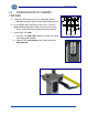
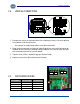
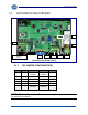
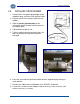
2.5.2. TB2 LOAD CELL
TB2 LOAD CELL
1
(–)Excitation 5V
2
(–)Sense
3
(+) Excitation
4
(+) Sense
5
Shield
6
(+) Signal
7
(–) Signal
JP7
(+) Sense Shorting Link
JP8
(–) Sense Shorting Link
2.5.3. TB3 WIRING CONNECTIONS, AC INPUT
1 AC AC Input
2 ACC ACC Input
3 Ground AC Ground
2.5.4. TB4 WIRING CONNECTIONS, COM1 (A), COM2 (B), AND
COM2 (C)
*Port should be set to RS485.
TB4 (A)
RS232
RS485
RS422*
PORT
1 Rx – Receive Data (–) RS485 RS422 (–) Rx COM1
2 Tx – Transmit Data (–) RS485 RS422 (–) Tx COM1
3 CTS – Clear-to-Send (+) RS485 RS422 (+) RX COM1
4 GND -- Ground GND GND COM1
5 RTS – Ready-to-Send (+) RS485 RS422 (+) Tx COM1
TB4 (B) RS232 RS485 RS422* PORT
1 Rx – Receive Data (–) RS485 RS422 (–) Rx COM2
2 TX – Transmit Data (–) RS485 RS422 (–) Tx COM2
3 CTS – Clear-to-Send (+) RS485 RS422 (+) Rx COM2
4 GND – Ground GND GND COM2
5 RTS – Ready-to-Send RS485 RS422 (+) Tx COM2
TB4 (C)
20 MA
RS485
RS422
PORT
1 (+) TX – Remote Display
Passive, 20 mA Output
COM2
2 (–) TX – Remote Display
Passive, 20 mA Output
COM2
3
(+) 7.5V Bluetooth
®
Technology Supply