Instruction Manual Portable Utility Scale 1155 SERIES SCALE WITH THE FB2255 INSTRUMENT © 2013 All rights reserved 51315 Rev.
AMENDMENT RECORD Portable Utility Scale Model 1155 With FB2255 Instrument Document 51315 Manufactured by Fairbanks Scales Inc. 821 Locust Kansas City, Missouri 64106 02/13 Created 02/13 Revision 1 02/13 Released new product 3 51315 Rev.
Disclaimer Every effort has been made to provide complete and accurate information in this manual. However, although this manual may include a specifically identified warranty notice for the product, Fairbanks Scales makes no representations or warranties with respect to the contents of this manual, and reserves the right to make changes to this manual without notice when and as improvements are made.
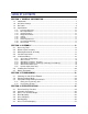
Table of Contents SECTION 1: GENERAL INFORMATION .................................................................. 7 1.1. 1.2. 1.3. 1.4. Introduction.............................................................................................................. 7 AC Power Settings .................................................................................................. 8 DC Power ................................................................................................................
Table of Contents SECTION 5: PARTS ................................................................................................. 28 5.1. FB2255 Instrument Assembly ................................................................................ 28 5.1.1. 5.1.2. 5.2. Pillar Assembly ...................................................................................................... 30 5.2.1. 5.2.2. 02/13 Parts List ................................................................................
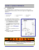
Section 1: General Information 1.1. INTRODUCTION The 1155 Series Scale is a combination of a roll-around cast iron base and a battery/AC powered digital indicator. NTEP and MC approved for “Legal for Trade” applications. APPLICATIONS Material handling Warehousing Inventory management Auditing Parts distribution Bag filling The 1155 Portable Platform Scale Base is constructed of cast iron with cast iron levers. • The weight display is an AC/Battery powered FB2255 Series Indicator.
Section 1: General Information 1.1. INTRODUCTION, CONTINUED NOTE: For commercial weighing applications, the scale must be 'placed-inservice' by a licensed scale technician. For product solutions, please call FAIRBANKS SCALES TECHNICAL SERVICES. Power supply must be used with a correctly grounded outlet. • Place the scale on a solid and level floor. • Avoid extremes in temperature, humidity, shock, moisture and dust. • The scale is factory calibrated and supplied ready to be assembled and used.
Section 1: General Information 1.2. AC POWER SETTINGS 110VAC The FB2255 is designed to operate from 80 to 260 volts AC, 50 to 60 HZ. ─ 110 VAC operations. ─ The Instrument is factory wired for 110 VAC and requires a three prong grounded outlet. 220 VAC The FB2255 has AUTO SWITCHING capabilities. ─ Rewire the power Cord according to the diagram. 1.3. DC POWER Batteries Five (5) Size “D” Alkaline batteries @ 1.5 Volts DC each.
Section 1: General Information 1.4. SPECIFICATIONS 1.4.1. INSTRUMENT APPROVALS CC 09-023 MC AM-5720 ETL ETL Listed Conforms to ANSI/UL STD 60950-1 Certified to CAN/CSA C22.2 STD NO. 60950-1-03 1.4.2. BASIC SPECIFICATIONS ENCLOSURE ABS, Black NEMA 1 DISPLAY 6-digits, One inch (1”) LCD, Green Backlight FRONT PANEL KEYS On/Off, Units, Zero, B/G, Net, Tare and Print UNITS lb, oz, kg, g and lb/oz, or custom GRADUATION SIZE 0.
Section 1: General Information 1.4. SPECIFICATIONS, CONTINUED 1.4.5. OUTPUTS PORT 1 Bidirectional Serial Port. Settings include OFF, RS232, and RS485. RS232 has 30+ updates a second PORT 2 Port 2 is used to interface to the PC2255 program, OR, Provide 20 mA passive, RS 232, or RS 485. 1.4.6. PC2255 • Computer software utility program is available for download using the Fairbanks Intranet.
Section 2: Assembly 2.1. NECESSARY TOOLS Small Slotted Screwdriver Phillips Screwdriver 10" Adjustable Wrench Common Pliers 2.2 WHEEL & PILLAR ASSEMBLY 1. Set the Scale Base Assembly (#4) sideways on the floor. 2. Insert a cotter pin (#17) through the small hole in one end of the first axle (#19). 3. Place a flat washer (#18) and a wheel (#16) onto the open end of the axle. 4. Insert the axle's other end through both holes in the base. 5. Place the second wheel (#16) onto the axle. 6.
Section 2: Assembly 2.2. WHEEL & PILLAR ASSEMBLY, CONTINUED 11. Screw the two (2) pillar rods (#1) into the two (2) tapped holes of the base. 12. Place the pillar (#2) over the pillar rods. ─ The cutouts face to the left and right of the platform 13. Insert the steelyard rod (#35) down through the pillar. ─ The bent hook is on top, and the loose swivel hook is on the bottom. 2.3. MOUNTING BRACKET KIT ASSEMBLY NOTE: The Adapter is partially assembled and packed with bubble-wrap.
Section 2: Assembly the pillar with the two (2) washers and nuts. 02/13 14 51315 Rev.
Section 2: Assembly 2.3. MOUNTING BRACKET KIT ASSEMBLY, CONTINUED 5. Tighten the pillar rod nuts using an adjustable wrench ─ Do not to touch the load cell while tightening each one. 6. On the bottom back-side of the scale’s base, lift up the lever end while placing the hook under the lever's pivot. ─ Do this while holding the hook on top of the pull rod. 7. Inserting the “S” hook: a. Insert the “S” hook (#3) through the eyelet of the load cell linkage cable adapter. b.
Section 2: Assembly 2.4. LOADCELL CONNECTIONS 1. Remove the screws on the back cover of the Indicator to access the main printed circuit board inside the enclosure. – Use caution to avoid pulling cables out of their connectors. 2. Bring the dressed end of the load cell cable through the strain relief connector on the back of the instrument, allowing enough cable on the inside to reach the load cell connection terminal on the main board. 3. Tighten strain relief as needed to grip the load cell cable. 4.
Section 2: Assembly 2.5. INSTRUMENT WIRING, CONTINUED JP3 TB2 TB5 J11 INTERNAL PROGRAM SWITCH TB4-A TB4-C TB4-B TB3 Printed Circuit Board (31308) 2.5.1. JP3 JUMPER CONFIGURATION) JP3 RS232 RS485 RS422* PORT 1-2 Out 120 Ohm Resistor 120 Ohm Resistor COM1 3-4 Out In Out COM1 5-6 Out In Out COM1 7-8 Out In Out COM2 9-10 Out In Out COM2 11-12 Out 120 Ohm Resistor 120 Ohm Resistor COM2 *Port should be set to RS485.
Section 2: Assembly 2.5.2. TB2 LOAD CELL TB2 LOAD CELL 1 (–)Excitation 5V 2 (–)Sense 3 (+) Excitation 4 (+) Sense 5 Shield 6 (+) Signal 7 (–) Signal JP7 (+) Sense Shorting Link JP8 (–) Sense Shorting Link 2.5.3. TB3 WIRING CONNECTIONS, AC INPUT 1 AC AC Input 2 ACC ACC Input 3 Ground AC Ground 2.5.4.
Section 2: Assembly 2.5.5. TB5 REMOTE SWITCH INPUTS 1 Ground 2 Ground 3 Ground 4 Print Connect to ground to perform programmed Print function 5 Tare Connect to ground to Tare off Gross weight 6 B/G Net Connect to ground to Select Gross/Tare displays 7 Zero Connect to ground to Zero Platform Weight 8 Units Connect to ground to change to alternate weight units 2.5.6.
Section 2: Assembly 2.6. INSTALLING THE INSTRUMENT 1. Connect the in-line phone plug adapter to the telephone plug, and then to the load cell cable. 2. Plug the end of the instrument cable into the adapter. 3. Slide the plastic gland bushing on the instrument section of cable into the center of the adapter plate. 4. Tighten-down the plastic nut. 5. Tuck the cable into the large plastic clips so it does not contact the load cell or become damaged. 6.
Section 2: Assembly 2.7. BATTERY INSTALLATION 1. Loosen the Indicator positioning knobs (located at each side), and then rotate the unit forward to access the back Battery (ABS) Enclosure. 2. Unscrew the two large knurled screws on the back of the Instrument 3. Remove the battery cover. 4. Insert five (5) alkaline “D” cell batteries. – Industrial ‘D’ size Energizer EN95 battery or equivalent is recommended for maximum operating time. 5. Refasten the back cover and tighten the knurled screws. 6.
Section 3: Programming 3.1. • POWERING ON AND OFF THE FB2255 To turn on the FB2255, press and hold the ON / OFF Key for two (2) seconds. – The Instrument will display “888888”, then a “1234567890” character display moving from right to left, followed by the revision of software. – Upon completing the warm-up, the FB2255 will display the actual weight on the scale. • To turn off the FB2255, press and hold the ON / OFF Key for two (2) seconds. 3.2.
Section 3: Programming 3.3.1. SETTING AND PROGRAMMING TIME 4. At SEtUP, press the RIGHT ARROW key Set-ti displays, followed by the current setting in HHMMSS. 5. Press the MENU key. 6. Key the new time setting with the 0-9 keys. 7. Press ENTER. 8. At the “12hr A” prompt, press the MENU key. 9. Use the ARROW KEYS to toggle through the option noted below. • 12hr A – 12 hour clock, currently AM. • 12hr P – 12 hour clock, currently PM. • 24 hour – Military time (1:00 PM = 1300 hours). 10.
Section 4: User Operations 4.1. FRONT PANEL KEY FUNCTIONS NOTE: Installing a jumper at J6, located at the upper-right corner of the main PCB Assembly, will disable the ON/OFF switch. This is not recommended in battery powered applications. KEY FUNCTION ON/OFF Turns the Instrument on or off. UNITS Switches between pre-programmed selectable weight units. ZERO Sets the display to zero, programmable: 2% or 100% of capacity.
Section 4: User Operations 4.2. OPERATING PROCEDURES • The Zero, Tare and the AZT functions require the displayed weight to be stable before these functions will operate. • The weight reading is stable if the variation in weight is less than the programmed MOTION BAND. 4.3. GROSS, TARE AND NET Weight NET There are three terms used when weighing an object’s or load’s amount. The NET WEIGHT (product only) is the GROSS WEIGHT (total amount) minus the TARE WEIGHT (container only).
Section 4: User Operations 4.4. BASIC WEIGHING Follow these steps for Basic Weighing. 1. Empty the platform. 2. Turn the scale ON. 3. Press ZERO. – When the display indicates “0”, it is ready for use. 4.5. Gross Weighing Follow these steps for Gross Weighing. 1. Press the GROSS/NET key, if required, to set display to GR (gross). 2. Press the ZERO key, if required, to set scale to “0”. 3. Place the container/object on the scale (Tare weight). 4. Read the Gross Weight on the display. 4.6.
Section 4: User Operations 4.7. GROSS/TARE/NET WEIGHING 1. Press the GROSS/NET key to display GR (Gross). 2. Press the ZERO key, if required, to set scale to “0”. 3. Place container/object on scale, noting the weight. 4. Press TARE. 5. Place material in container or add objects. 6. Note the Net Weight on the display. 7. Press the GROSS/NET key to switch to Gross. Read the Gross Weight on the display. 02/13 27 51315 Rev.
Section 5: Parts 5.1. FB2255 INSTRUMENT ASSEMBLY 5.1.1. PARTS LIST ITEM(S) PART NO. QTY 1 2 3 4 5 6 7 8 9 10 11 12 13 14 15 16 17 18 19 26 27 30 34 14230 1 KIT, LOAD CELL ASSY 12643 1 HOOK S 17617 17613 20176 26299 11263 1 1 1 1 1 MOUNT, CABLE TIE TIE, WIRE BRACLET HANDLE ASSY CLIP, CABLE 11119 11092 11103 11076 15716 11126 14904 32445 32449 17545 32456 50801 12083 6 2 2 2 4 4 4 1 1 1 8 IN 1 1 02/13 DESCRIPTION WASHER-PLAN-FLAT NO. 10 WASHER-LOCK-MED SPRINT NO.
Section 5: Parts 5.1.2. 02/13 PARTS DIAGRAM 29 51315 Rev.
Section 5: Parts 5.2. PILLAR ASSEMBLY 5.2.1. PARTS LIST ITEM(S) PART NO.
Section 5: Parts 5.2.2. 02/13 PARTS DIAGRAM 31 51315 Rev.
Portable Utility Scale Model 1155 Series Manufactured by Fairbanks Scales, Inc. 821 Locust Street Kansas City, MO 64106 www.fairbanks.