
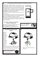
Installation Instructions and Use and Care Info


15
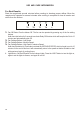
Cleaningmetalgreaselters
The metal grease lters can be cleaned in hot detergent so-
lution or washed in the dishwasher. They should be cleaned
every 2 months, or more frequently if use is particularly heavy.
• Remove the lter, pushing the lever towards the back of
the unit and at the same time pulling downward.
• Wash the lter without bending it, leave it to dry thorou-
ghly before replacing (if the surface of the lter changes
color over time, this will have absolutely no effect on its
efciency).
• Replace, taking care to ensure that the handle
faces forward.
• Cleaning in dishwasher may dull the nish of the
metal grease lter.
Replacing Activated Charcoal Filter
The Activated Charcoal Filters are not washable
and cannot be regenerated, and should be replaced
approximately every 4 months of operation, or more
frequently with heavy usage.
• Remove the charcoal lter by rotating it clockwise ( backwards)
until it unlocks from the motor housing and pull off sideways.
• To re-insert each charcoal lter, place up against the side
of the blower and push it inward. Then turn the charcoal
lter clockwise (forward) until it ts into place.
Replacing the two 35W Halogen GU10 bulbs
• Turn off electrical supply before replacing bulbs, and make
sure bulbs are cool to touch before proceeding.
• Carefully remove the snap-on lamp cover using a at
head screwdriver by levering it down from under the
metal ring.
• After the snap-on lamp cover is down remove the halogen
lamp at the base and turn slightly to the left and the pull
out from the connector and turn slightly to the left.
• Replace the lamp with a new one of the same type,
making sure that you insert the two pins properly into the
housings on the lamp holder.
• Replace the snap-on lamp cover.
• Once the bulb pins are in place turn slightly to the right
to secure.
EN
7
7
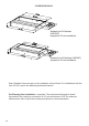
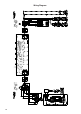
INSTALLATION
Fitting the Hood canopy
BEFORE FITTING THE HOOD TO THE WALL UNIT, PROCEED AS FOLLOWS:
• Disconnect the wires to the Commands at the connectors.
• Disconnect the wires to the Light at the con-
nectors.
• The Hood can be installed directly on the
underside of
the wall unit (Minimum 650 mm
from the Cooker Hob).
• Create an opening in the bottom of the wall unit,
as shown.
• Insert the hood until the side supports snap into
place.
• Fasten using the 10 screws 12a provided.
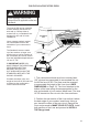
• Lock in position by tightening the screws Vf from
underneath the hood.
• Open the suction panel by turning the specific knob.
• Disconnect the panel from the hood canopy by sliding the
fixing pin lever.
• Remove grease filters.
• Screw the Frame into place
using the 6 scr
ews 12f, re-
connect the wires to the
Commands and Light, re-
place the metal grease filter
and the Panel.
260
13
495 - 675