
Owner`s manual

45
015885 rev 10-00
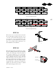
STEP 34
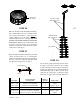
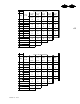
The access doors to the bin are located in
the second ring from the bottom (32” door)
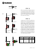
or in the second and third rings from the
bottom (64” door). Special sheets are
provided to accommodate the door frames
(fig. c & d). These sheets will need to be
field drilled for the stiffeners.
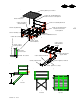
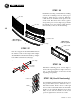
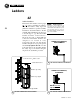
STEP 35
Insert the appropriate door frame (32” or 64”)
into the opening created by the special length
sheets. Use sealer tape on all four sides of
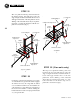
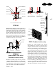
the opening. Attach the cover to the frame
at the hinges and install the lock assembly
(fig. e). Bolt the outer door clip to the side
wall on the hinge side to keep the door cover
fixed in position when open (fig. f). Fasten
the striker plate to the door jamb (fig. g).
Adjust the cam so that the door will close
tightly. Use this same procedure to install
the lock in the upper access door.
DOOR 67 1/2"
SP
SP
SP
SP or DP
c
32” door in a single punched ring
d
64” door in a single punched ring
e
f
g
door frame
striker plate
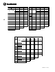
DOOR
67 1/2"SP
SP or DP
SP
SP
58"
123 1/2"