
Owner`s manual

44
015885 rev 10-00
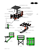
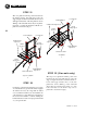
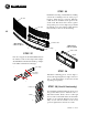
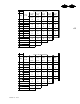
STEP 32 (2 fan units only)
The step across platform will be positioned
between the two fan platforms. Locate the
support angles and braces such that the floor
level will approximate that of the fan
platforms. Some drilling of the sidewall
sheets may be required. Use 5/16” x 1” bin
bolts and nuts for the all the step across
platform construction (fig b).
STEP 31
The door platform will be positioned between
the ladder and the fan platform. Locate the
support angles and braces such that the floor level
will approximate that of the fan platform. Some
drilling of the sidewall sheets may be required.
Use 5/16” x 1” bin bolts and nuts for all the door
platform construction (fig. a).
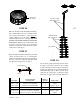
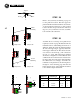
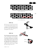
STEP 33
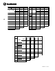
Continue to raise the bin using the proper gage
of sidewall sheet as given in the chart on pages
48 and 49. For every two rings that are added
a set of stiffeners will need to be installed. On
odd ring bins a 1 ring stiffener is supplied for
the bottom. In addition, continue adding the
ladder and Vac-U-Vent control pipes if included
on your specific bin.
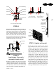
0159259 railing 37”
post 10033147
015257 right hand
angle 45 1/2”
015258 toe board 37”
015256 left hand angle 45 1/2”
020037
floor piece
015101 railing 26”
post 10033147
015099 right hand
angle 38 1/2”
015100 toe board 26”
015098 left hand
angle 38 1/2”
020026
floor piece
015102
support braces
door platform
a
step accross platform
b
015102
support braces
015103
railing support
015103
railing support