
Owner`s manual

42
015885 rev 10-00
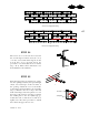
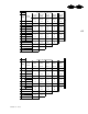
STEP 29
Refer to the system layout drawing on page 23
for the platform location. Bolt the upper fan
platform bracket inside the stiffeners at each side
of the fan entrance frame (fig. a). The vertical
location should correspond to the size of fan used
(fig.s b-e). If your unit has two fans, assemble
both of them at the same time.
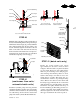
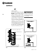
STEP 30
Assemble the door and step across platform (if
required) as shown on page 44. Raise the bin and
install the next two sidewall rings and next set of
stiffeners. Attach the lower fan platform bracket
56” below the upper (fig. k, page 43). Fasten the
main support channels, the knee braces and the
cross braces as shown in fig. j. All connections
use 3/8” x 1” bolts. The main support channel
should be at a height based on the chart below. If
a different model or brand is used, measure from
its support leg to the center of the outlet and adjust
the dimensions accordingly. Assemble the
remainder of the platform as shown in figures h
through m on the following page. The fan and
heater unit may be set on the platform and bolted
to the entrance adapter at this time.
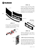
a
b c
d e
sidewall
stiffener
bracket
3rd full
sidewall ring
Sukup 28” fan
Sukup 24” fan
4th full
sidewall ring
dim x
dim x
f g
Sukup Fan Outlet Height dim x figure
24" 16 1/2" 2 1/4" g
28" 18 1/4" 1/2" g
38" 23 5/8" 4 7/8" f
44" 28 3/4" 10" f
Sukup 44” fan Sukup 38” fan