
Owner`s manual

41
015885 rev 10-00
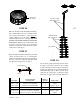
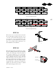
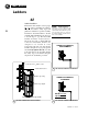
STEP 26
Raise the bin and add the third full sidewall ring.
The outside ladder needs to be assembled as the
bin is being raised. Refer to pages 50-53 for
ladder instructions. At this time bolt the fan
entrance frame(s) into the opening(s). The wide
portion of the frame should go toward the
bottom. Field drill the holes for the tension ring
in the fan entrance header. Also install the
stiffeners on either side of the fan entrance frame
at this time as well (fig. d)
stiffeners at the
fan entrance
d
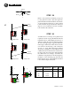
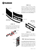
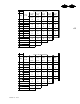
STEP 27
Raise the tank and add the fourth ring of sidewall
sheets. Install another set of intermediate
stiffeners beneath the first set previously installed.
The top of the lower stiffeners will splice with
the upper by nesting inside of it (fig. e).
e
first and second full
width sidewall sheets
third and fourth full
width sidewall sheets
69 5/8” stiffener
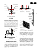
STEP 28
If your bin is equipped with Vac-U-Vents insert
the upper control pipe section into the coupling
bolted to the angle on the lower Vac-U-Vent sheet.
Install eye bolts at the bottom of the first and third
full sidewall rings (fig. f). These eye bolts act as
guides for the control pipes. As the bin is being
built add control pipes as shown in the chart below.
f
eye bolt
neoprene washer
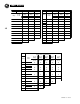
bin height
eye bolt placement
from top of bin
number of
eye bolts
length of pipe
7 1/2 R 19'-9" bottom of 1st & 3rd full ring 2 3 @ 63"
8 1/2 R 22'-5" bottom of 1st, 3rd & 5th full ring 3 3 @ 63" / 1 @ 31"
9 1/2 R 25'-1" bottom of 1st, 3rd & 5th full ring 3 4 @ 63"
10 1/2 R 27'-9" bottom of 1st, 3rd, 5th, & 7th full ring 4 4 @ 63" / 1 @ 31"
11 1/2 R 30'-5" bottom of 1st, 3rd, 5th, 7th, & 9th full ring 5 5 @ 63"