
Owner`s manual


27
015885 rev 10-00
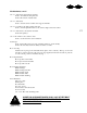
3/4"
REF
Leave this
bolt out for
the splice.
1/4" REF
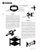
NOTE: The bottom of the
sidewall should rest
approximately 1/4"
off of the concrete slab.
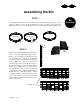
STEP 5
Locate the sign sheets in their previously
determined location and fasten them to the sidewall
by field drilling as shown in fig. i on page 26.
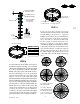
Install 63 3/16” stiffeners (two per sidewall sheet)
in the vertical seams at all sheets on both rings
(fig. e). Use 5/16” x 1” bin bolts and flange nuts
for this connection, with the bolt heads to the
inside. Use a drift pin or screw driver to lift the
sidewall rings slightly when installing the stiffener
as they will protrude about 1/4” beneath the sheet
edge. Omit the stiffeners on either side of the fan
entrance frame at this time (fig. f). The top hole in
the stiffener aligns with the hole in the second
outside hill of the first full width sidewall ring
(fig. e).
e
second hill of the first
full width sidewall ring.
sides of the fan
entrance frame
f
stiffeners
sheet joint on top,
no joint on bottom
no joint on top,
sheet joint on bottom
etc.
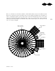
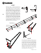
STEP 6
Locate the Ezee Dry Center Collar in the center of
the bin at the height shown in Fig. g on a center jack
platform. The collar flange with (8) 9/16” holes should
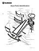
be to the top. Install four of the Ezee Dry Rafter
Purlins at the quarter points of the bin. Bolt each to
the center collar using (2) - 1/2”x1 1/2” grade 5 bolts
with nut and flat washer and to the tension angle
using (2) - 1/2”x1 1/2” grade 5 bolts with nut and
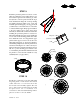
flatwasher. Install the remaining rafters alternating left
hand and right hand assemblies (fig. h and page 26 -
fig. j), but do not fully tighten the rafter bolts until the
perforated inner roof sheets are installed. Make sure
that the rafters are not “racked” and the center collar
is level and not twisted before proceeding. If these
conditions are present, correct by attaching a
comealong to the center collar and bin wall; tighten
to remove any twist or rack. Leave the come-along in
place until the inner roof is completely assembled.
‘A’
Bin Dia “A”
18’ 5’ 7 1/4”
21’ 6’ 4 1/4”
24’ 7’ 1 1/8”
27’ 7’ 10 1/8”
30’ 8’ 7”
g
18’
L
R
L
R
L
L
L
L
L
L
L
R
R
R
R
R
R
R
L
R
21’
L
L
L
L
L
L
L
L
L
R
R
R
R
R
R
R
R
R
L
24’
27’
30’
R
L
L
L
L
L
L
L
L
L
L
L
L
R
R
R
R
R
R
R
R
R
R
R
R
L
R
R
L
L
L
L
L
L
L
L
LL
L
L
L
R
R
R
R
R
R
R
R
R
R
R
R
R
R
R
R
R
R
R
R
R
R
R
R
R
L
L
L
L
L
L
L
L
L
L
L
L
L
L
L
h
note: alternate right hand
and left hand purlins
note: In these bin purlin
location drawings, the dark
lines indicate the locations
of the 4 quarter point
purlins to be installed first.
8 holes on collar top
4 holes on collar bottom
splice holes
note: this first stiffener
to be installed is
63 3/16” long.
flange nuts
Install this bolt with the
head on the inside.