
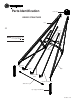
Owner`s manual


26
015886 5-02
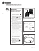
door
fan
entrance
fan
entrance
door
fan
entrance
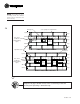
ring built in step 2
top ring
2nd ring
3rd ring
4rth ring
5th ring
top ring
2nd ring
3rd ring
4rth ring
5th ring
SHEET LAYOUT WITH ONE FAN
SHEET LAYOUT WITH TWO FANS
UPPER SIDEWALL LAYOUT SHOWING DOOR AND FAN ENTRANCE LOCATIONS
a
rows of holes
for stiffeners
(ring built during
step 2)
rows of holes
for stiffeners
(ring built during
step 2)
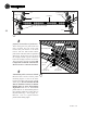
58”
58”
58”
58”
17 ga
10 ga
15 ga
17 ga
15 ga
17 ga
10 ga
15 ga
17 ga
15 ga
3 1/8” spacing for roof attachments
flashing holes
flashing holes
Align the 10 gage sidewall sheets in the second ring so that the
flashing hole punching is toward the top.
NOTE:
After building the dryer
assembly, follow the sidewall
layout below to install fans and
doors correctly.