
Installation Guide

– 8 –
1.13.4.1 Same as the first platform, if more than one platform is connected to the “second”
platform, install a dual platform connector on additional support tubes as needed,
bring the connectors up until they touch the bottoms of the corner pockets and
tighten all setscrews securely. Planning will be required to make sure not only that
the connectors are oriented in the correct direction, but also that the subsequent
platforms are supported by at least two legs as the deck is assembled, before
installing the legs in the platform (Refer to Section 1.13.8 for other requirements).
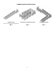
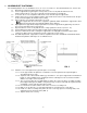
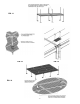
1.13.5 If the platform connector is in a location where a guard, filler section or corner post (typically
the outer edge of the deck) is required, install the 1-1/2” square x 35-1/2” long tube provided
through the platform corner pocket and connector until it aligns (approximately) with the
bottom of the connector and tighten all setscrews securely (FIG. 10).
Installation of platform guards and other components is described elsewhere in the manual.
1.13.6 In all locations where there will be no guards or filler sections install the 1-1/2” square x
10-1/8” long tube provided through the platform corner pocket and connector. Center the
stub (approximately) between the bottom of the connector and the platform walking surface
making sure all the setscrews contact the stub and tighten setscrews securely (FIG. 10).
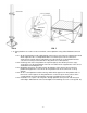
1.13.7 At this point there will be one or more support tubes extending above the platform deck
which will
not
be used to attach a guard, filler section or corner post. Mark these support
tubes at the top of the corner pocket and cut the leg off at or slightly below the mark
(FIG. 11).
The appearance and quality of the cut is not critical since these areas will be covered with a
plate in later steps. What is critical is the support tube not stick up past the deck far enough to
interfere with the plate when it is installed.
1.13.8 Add additional platforms by repeating steps 1.13.4 thru 1.13.7 until deck is complete.
The requirements below must be followed regardless of platform’s position in the deck.
1.13.8.1 There should always be one leg and one “stub” in a dual platform connector. This
may require repositioning a connector from the way it was initially oriented (or
replacing a stub with a support tube) depending on the configuration.
Never use two “stubs” without a leg in a dual platform connector.
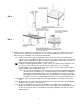
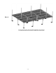
1.13.8.2 Where four platforms come together, the two legs should be oriented so that they
are diagonally opposite from each other (FIG. 12).
1.13.8.3 Whenever possible, especially where four platforms come together, the dual
platform connector on one side of a platform should be oriented in the opposite
direction from the other side and the orientation should then be alternated as the
deck is created (FIG. 14).
1.13.8.4 Regardless of connector orientation, make sure there is a minimum of two legs
installed in each platform’s corner pockets (FIG. 15).
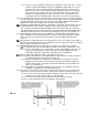
1.13.9 Once the deck is complete all areas where platforms connect that are not used to attach a
guard, filler section or corner post must be covered with a Corner Cover Plate (FIG. 13).
1.13.9.1 Use the corner cover plate provided to mark the location of the hole in the deck and
drill four holes between 0.129” and 0.133” dia. (#30 drill).
1.13.9.2 Use the four 1/8” dia. rivets provided to attach the corner cover plate.
1.13.9.3 Use two cover plates where four platforms come together.
FIG. 10