
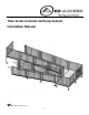
Installation Guide

– 5 –
1. ASSEMBLE/SET PLATFORMS:
Our standard platform sizes are available in; 5’ x 5’, 6’ x 6’, 5’ x 6’ and 5’ x 7’. Consult manufacturer for custom sizes.
1.1 Determine the platform height required for the location.
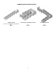
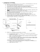
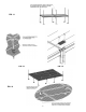
1.2 Insert a support tube (leg) through a corner pocket at corner of the platform and into the foot
(FIG. 4). Orient all feet so they do not protrude past the perimeter of the platform.
1.3 Use hole in the foot as a template to drill 11/32” or 3/8” hole through the support tube.
1.4 Install a 5/16”-18 x 3” long hex bolt through the support tube and foot then secure with the 5/16”-18 nylon
insert locknut and tighten the thumb screw securely.
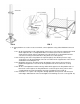
1.5 Ensure that the correct length support tubes are used.
The support tubes are also used to support the guardrails. When installed, the support tubes must
extend at least 24” above the platform walking surface (FIG. 5).
1.6 Adjust platform to approximate height required then secure the support tube by tightening setscrews in
the corner pocket with 3/16” hex key wrench.
1.7 Repeat at all four corners of the platform unless using a platform connector (refer to 1.12)
1.8 Position platform in final location then make height and level adjustments as needed.
1.9 Check to confirm all setscrews securing the support tubes are fully tightened and the support tubes
cannot move with respect to the platform (a total of eight, two in each corner).
1.10 Assemble all platforms, support tubes and feet required in this fashion. Guardrails and handrails will be
installed after platforms and ramps are assembled and set.
FIG. 4 FIG. 5
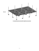
1.11 Platforms over 3 feet high from the ground require cross bracing.
1.11.1 Insert support tubes into platform, assemble the feet and set platform at required height as
described in previous steps.
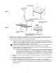
1.11.2 Separate ends of brace bands until they go around the 1-1/2” square support tube and install four
bands on each leg with the part containing bolt holes at 90 degrees from each other and in line
with the outer edge of the foot (FIG. 6).
1.11.3 The cross brace will come assembled with one bolt in the center. The brace assembly should be
placed approximately in the middle of the platform legs on all four sides with the top brace bands
a minimum of 2 feet from the bottom brace bands.
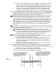
1.11.4 If needed for the location, trim the ends of the cross brace assembly to fit.
1.11.5 Drill one 11/32” dia. hole on center approximately 1/2” from both ends of each brace.
1.11.6 Install cross brace assembly using four 5/16”-18 x 1-1/2” long square neck carriage bolts, nuts
and washers in the desired location (FIG. 7).
1.11.7 Tighten all fasteners securely.