
Installation Guide

– 17 –
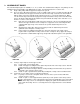
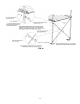
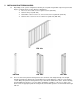
FIG. 25 FIG. 26
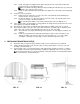
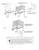
FIG. 27
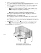
5.3 If a single platform is used as a landing at the top of the system with the ramp approach parallel to
the door:
5.3.1 Place one guard corner post over the support tube (leg) extending out of the platform
corner pocket opposite both the door and ramp (FIG. 25). Do not tighten set screws.
All four connector brackets should be oriented in toward the platform.
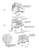
5.3.2 Place two guards over the support tubes (legs) protruding out of the platform corner
pockets opposite the corner post connector brackets (FIG. 26) and engage tabs on the
guard sections into connector brackets on corner post. Do not tighten set screws.
5.3.3 Place guard filler section over the remaining support leg with the connector brackets
oriented toward the outside of the platform (FIG. 27).