
Installation Guide

– 14 –
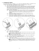
4.6 Level the universal support tube brackets and secure in level position using a 9/16” wrench.
4.7 Adjust the ramp height until the transition plate is resting flat on the platform surface. Tighten both set
screws in the universal support tube bracket securely then repeat process on the opposite side of the
ramp.
4.8 Repeat the process on the lower end of the ramp or ramp run, again insuring that the transition plate
rests flat on the platform surface.
4.9 Use same procedure to install the support tubes (legs) and feet on the center support brackets if
present.
4.10 Have a helper site down the top edge of the ramp side rail and adjust ramp height where the ramps
connect until top edge of ramp side rails are aligned then tighten the set screws in the support tube
brackets securely.
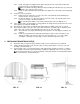
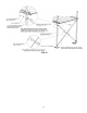
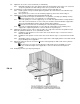
It is important that the support tubes (legs) are adjusted correctly and the ramp sections are
aligned, neither bowing down or up (see FIG. 22 for correct positioning). Failure to adjust properly will
result in difficulty attaching the ramp guards and handrails later in the assembly.
4.11 Repeat this procedure when assembling and placing ramp section(s) between platforms until the
lowest section is reached.
FIG. 22
4.12 The lowest ramp run will always begin with a starter section. This section requires the same
installation procedure with two exceptions.
4.12.1 There is no end support assembly on the tapered end of the ramp section and, since it rests on
the ground, no support leg is required.
4.12.2 Only one transition plate is required at the top of the ramp run.
4.13 Install plugs in the top of all support legs.
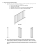
4.14 Ramps over three feet high from the ground require cross bracing.
4.14.1 Insert legs into the ramp and set ramp at the required height as described in previous steps.
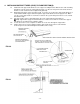
4.14.2 Assemble the cross brace using the 5/16”-18 x 1-1/2” long hex bolt, nylon insert locknut and
washer through the center hole in both braces.
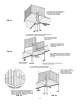
4.14.3 Separate the ends of brace bands until they go around the 1-1/2” square tube and install two
bands on each leg. Orient the bands so that the side with the holes extends under the ramp (FIG.
23).
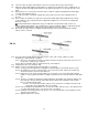
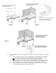
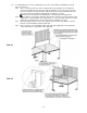
4.14.4 The brace assembly should be placed approximately in the middle of the ramp legs with the top
brace bands as far as practical from the bottom brace bands, but a minimum of 24”, and the
brace assembly under the ramp.
4.14.4.1 If needed for the location, trim the ends of the brace assembly to fit. Remove all
sharp edges after cutting with a file or by sanding.
4.14.5 If the ends with the pre-drilled holes are cut to fit the location, drill an 11/32” or 3/8” diameter hole
on center approximately 3/8” to 1/2” from the end of each brace.
4.14.6 Install brace assembly using four 5/16”-18 x 1-1/2” long carriage bolts, nuts and washers in the
desired location (FIG. 23).
4.14.7 Tighten all fasteners securely.