
Installation Guide

– 12 –
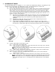
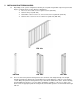
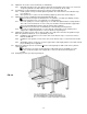
2.4.3 Install end support assembly brackets (FIG. 16a) at both ends of the ramp run (this will
require two pairs of end support brackets).
Make sure that the two larger diameter studs protruding from the brackets are positioned
toward the outer end of the ramp section.
2.4.4 Install one pair of guard brackets (FIG. 16b) at the mid-point of each ramp section making up
the run.
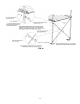
2.5 If using as a turn or turn-back:
2.5.1 Ramp must be positioned to one side or the other of the platform and should always be
positioned to the outside of the turn.
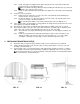
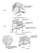
2.5.2 Position the ramp to one side of the platform so that the edge of the transition plate is 4½”
from the outer edge of the platform (FIG. 17).
The transition plate will be secured to the platform later in the assembly process.
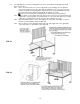
2.6 If the system requires an intermediate “resting” platform, the ramps must be positioned in the center
of the platform (see FIG. 28 and FIG. 32).
2.7 Repeat this procedure when assembling and setting ramp runs until the lowest run is reached.
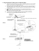
2.8 The lowermost ramp section (the only section that contacts the ground directly) is called the starter
ramp section. This section can be identified by the taper at one end of the ramp.
2.8.1 The underside of the taper will sit directly on the ground so an end support assembly is not
required.
2.8.2 Install (1) pair guard brackets (FIG 16b) at mid-point of ramp section and either an end
support assembly, if the starter section is the only ramp in the run, or a center support
assembly if connecting to another ramp section as described in previous steps.
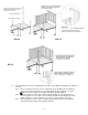
3. INSTALLING TRANSITION PLATE(S)
3.1 A transition plate is required at any point that a ramp section or ramp run meets a platform.
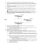
3.2 Install a transition plate into each end of the ramp section(s) by turning the section(s) over, then
inserting as shown in FIG. 18.
3.3 Position ramp section so the transition plate is fully supported by the platform surface as shown in
FIG. 19. Make sure that the top transition plate overlaps the supporting surface as far as possible.
The transition plates may not rest flat on platform at this point and this is normal (transition plates
will be secured later, as shown in FIG. 48).
FIG. 17 FIG. 18 FIG. 19