
Installation Guide

– 11 –
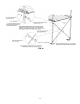
2. ASSEMBLE/SET RAMPS:
Five standard ramp lengths are available, 2’, 3’, 4’, 5’, and 6’. The standard starter ramp is 6’ long. Ramps are also
available in 48” and 54” widths (clear width between curbs). Consult manufacturer for custom sizes.
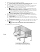
2.1 Begin setting ramps with the uppermost ramps in the system.
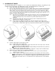
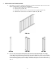
2.2 There are three different bracket types used to assemble ramp sections (see FIG. 16a, FIG. 16b and
FIG. 16c). All three bracket types are fit into the side rail of the ramp section and are best installed
with the ramp section placed upside down using the 5/16-18” x 1.5” hex bolts and washers. Make
sure the narrow edge of the bracket engages the trough formed in the ramp section side rail and the
holes in the bracket align with the threaded inserts preinstalled in the ramp section side rails. Use ½”
wrench or socket to secure fasteners.
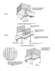
2.2.1 End support assembly bracket (FIG. 16a): These brackets come in a left and right pair and
attach to the upper and lower end of a ramp run to support the ends of the ramp run when
combined with support legs. These brackets also provide attachment points for the
guardrails.
2.2.2 Guard brackets (FIG. 16b): This pair of brackets provides an attachment point for the
guardrails at the mid-point of a ramp section.
2.2.3 Center support assembly bracket (FIG. 16c): This pair of brackets joins ramp sections
together and is required where ramp sections meet in a ramp run. They support the ramp at
this point when combined with support legs and provide attachment points for the guardrails.
FIG. 16a
FIG. 16b
FIG. 16c
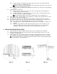
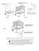
2.3 If using a single ramp as the first upper section:
2.3.1 Lay the ramp section upside down.
2.3.2 Install end support assembly brackets (FIG. 16a) at both ends of the ramp section. This will
require two pairs of end support brackets.
Make sure that the two larger diameter studs protruding from the brackets are positioned
toward the outer end of the ramp section.
2.3.3 Install one pair of guard brackets (FIG. 16b) at mid-point of ramp section in similar manner.
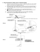
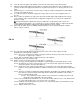
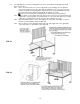
2.4 If using two or more ramp sections for uppermost ramp run:
2.4.1 Lay ramp section end-to-end upside down on a level surface (a level surface will make
sections easier to connect).
2.4.2 Install one pair of center support brackets (FIG. 16c) at each junction of two ramp sections.
It is critical that the center support bracket be positioned equally with respect to threaded
inserts in the ramp sections to avoid problems aligning the guards and handrails later. This
may require measuring. There is a centering mark on the support bracket to assist with this
process.