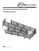
Titan Series Commercial Ramp System Installation Manual Manufactured in the USA –1–
BEFORE YOU BEGIN SYMBOL AND SYMBOL MEANINGS WARNING SYMBOL FIG. A FIG. A depicts the WARNING symbol. Black and White, as shown at right, is the preferred WARNING symbol color. This symbol may appear in various colors and in conjunction with other symbols. When the word WARNING is written, it will be in all caps and bold font.
MAINTENANCE: Proper maintenance and upkeep to the system is vital. DO NOT USE if ramp guards, handrails, or supports are damaged or unstable. Do not use if surface is covered with ice and/or snow. Accumulation must be shoveled and the tread surface swept clean before use. At all times, keep system clear of dirt, leaves, and other debris that may accumulate on the surface. Confirm that the system is correctly leveled and positioned securely. Periodically check for ground shifts.
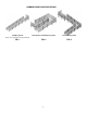
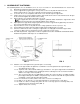
COMMON RAMP CONFIGURATIONS Straight System Turn Back (or Switchback) System Corner Turn System FIG. 2 FIG. 3 (Over 30’ Long Requires Resting Platform) FIG.
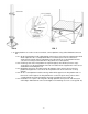
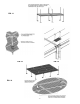
1. ASSEMBLE/SET PLATFORMS: Our standard platform sizes are available in; 5’ x 5’, 6’ x 6’, 5’ x 6’ and 5’ x 7’. Consult manufacturer for custom sizes. 1.1 Determine the platform height required for the location. 1.2 Insert a support tube (leg) through a corner pocket at corner of the platform and into the foot (FIG. 4). Orient all feet so they do not protrude past the perimeter of the platform. 1.3 Use hole in the foot as a template to drill 11/32” or 3/8” hole through the support tube. 1.
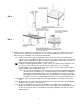
FIG. 6 FIG. 7 1.12 If two platforms are used to create a turn-back, connect platforms using a Dual Platform Connector Kit. 1.12.1 On the first platform, install a dual platform connector on each of the two support tubes which will be adjacent to the second platform. Make sure that the pocket of the connector is oriented to the outside of the first platform, in the direction of the second platform and the setscrews are facing in a direction where they will be accessible (FIG. 8). 1.12.
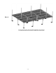
FIG. 8 FIG. 9 1.13 Platforms can be combined, in any direction, to create a deck as long as the adjacent sides are the same length. The initial steps are similar to Sec. 1.12, using two platforms to create a turn-back. Refer to the project drawings for specific deck configuration. 1.13.1 On the first platform, install a dual platform connector on each of the two legs that will be adjacent to the second platform.
1.13.4.1 Same as the first platform, if more than one platform is connected to the “second” platform, install a dual platform connector on additional support tubes as needed, bring the connectors up until they touch the bottoms of the corner pockets and tighten all setscrews securely.
FIG. 11 FIG. 12 FIG. 13 FIG.
FIG.
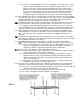
2. ASSEMBLE/SET RAMPS: Five standard ramp lengths are available, 2’, 3’, 4’, 5’, and 6’. The standard starter ramp is 6’ long. Ramps are also available in 48” and 54” widths (clear width between curbs). Consult manufacturer for custom sizes. 2.1 Begin setting ramps with the uppermost ramps in the system. 2.2 There are three different bracket types used to assemble ramp sections (see FIG. 16a, FIG. 16b and FIG. 16c).
2.4.3 2.5 2.6 2.7 2.8 Install end support assembly brackets (FIG. 16a) at both ends of the ramp run (this will require two pairs of end support brackets). Make sure that the two larger diameter studs protruding from the brackets are positioned toward the outer end of the ramp section. 2.4.4 Install one pair of guard brackets (FIG. 16b) at the mid-point of each ramp section making up the run. If using as a turn or turn-back: 2.5.
4. INSTALLING SUPPORT TUBES (LEGS) TO RAMP SECTION(S): 4.1 4.2 4.3 4.4 4.5 Install universal support tube brackets to the support assembly brackets with the 3/8” studs extending through the curved slots in the support tube brackets. Use two 3/8”-16 nylon insert locknuts and 3/8” washers at each location but do not tighten fully (FIG. 20).
4.6 4.7 Level the universal support tube brackets and secure in level position using a 9/16” wrench. Adjust the ramp height until the transition plate is resting flat on the platform surface. Tighten both set screws in the universal support tube bracket securely then repeat process on the opposite side of the ramp. 4.8 Repeat the process on the lower end of the ramp or ramp run, again insuring that the transition plate rests flat on the platform surface. 4.
FIG.
5. INSTALLING PLATFORM GUARDS: 5.1 Depending on the system configuration, following are four platform guardrail component options that may be used that may be used in different combinations: Five-foot, six-foot and seven-foot guard sections (FIG. 24a) Guard corner post (FIG. 24b) Guard filler sections for five-foot, six-foot and seven-foot platforms (FIG. 24c) Guard corner sections for five-foot and six-foot platforms (FIG. 24d) FIG. 24a FIG. 24b 5.2 FIG. 24c FIG.
FIG. 25 FIG. 26 FIG. 27 5.3 If a single platform is used as a landing at the top of the system with the ramp approach parallel to the door: 5.3.1 5.3.2 5.3.3 Place one guard corner post over the support tube (leg) extending out of the platform corner pocket opposite both the door and ramp (FIG. 25). Do not tighten set screws. All four connector brackets should be oriented in toward the platform.
5.4 If a single platform is used as a landing at the top of the system with the ramp approach at 90 degrees to the door: 5.4.1 Place one guard corner post over the support tube (leg) extending out of the platform corner pocket adjacent to the door and opposite ramp. Two of the corner post connector brackets should be oriented toward the support tube where the guard will attach and the other two away from the platform (FIG. 28). Do not tighten set screws.
5.5 If platforms are used to create a turn back (or switchback): 5.5.1 Both platforms will use the same guard components and follow the same steps as in section 5.3 except one platform is the mirror image of the other (see FIG. 25, 26, 27 & 30). 5.6 If a platform is used in a 90 degree turn from one ramp to another ramp (FIG. 31): 5.6.1 Install a guard corner post and two platform guards in the same manner as described in steps 5.3.1 and 5.3.2. 5.6.
FIG. 31 FIG. 32 FIG. 33 FIG.
6. INSTALLING RAMP GUARDS: 6.1 6.2 Ramp guards come in left and right pairs and are not interchangeable from side-to-side. For all ramp sections other than the starter section: 6.1.1 Install the Ramp Guard Post Spacers over the 5/16”-18 studs protruding from the brackets previously installed on the ramp section with the long end of the spacer pointing up (FIG 35). 6.1.2 Attach the ramp guard to the ramp section by positioning the lower holes in the ramp guard posts over the studs. 6.1.
7. INSTALLING HANDRAILS: 7.1 Ramp handrails are supplied in left and right pairs and are not interchangeable. 7.1.1 Starting at the lower end of ramp system, attach first handrail section by aligning holes in the handrail brackets with the holes in the guard vertical posts. Secure with one 5/16”-18 x 2 1/4” button head socket cap screw, washer and nylon insert lock nut as shown in FIG. 37 but do not tighten fully. 7.1.2 Repeat on the remaining handrail brackets securing bolts but not fully tightening. 7.1.
8.2 8.3 At the bottom of the ramp (i.e., the starter ramp at the ground or ramp runs starting at a resting platform), install two lower termination loops into the ends of each handrail (FIG. 40). 8.2.1 Install upper portion of loop to handrail using a 4” joiner. Tighten set screw enough to hold in place, but leave loose enough to rotate. 8.2.2 Rotate lower portion of loop until it lines up with ramp guard post. Mark center, then drill 5/16” or 11/32” hole through post.
8.4 At a turn platform on the outside, non-turn side (both where a the top of a ramp meets a platform and where a ramp starts at a platform) as shown in FIG. 41: 8.4.1 Use a ring joiner to attach one 5 degree elbow to ramp handrail. 8.4.2 Hold 90 degree elbow in position and mark for trimming. 8.4.3 After trimming, test fit elbow. 8.4.4 When fit is confirmed, install threaded insert into short end of elbow with a hammer. 8.4.5 Connect long side to 5 degree elbow with a ring joiner. 8.4.
8.6 At a turn-back platform on the inside, turn-back side (FIG. 43): 8.6.1 Hold two 90 degree elbows in position and mark for trimming. 8.6.2 After trimming, test fit elbows, handrail brackets and spacers. 8.6.3 Attach long legs of elbows in the middle with a ring joiner, and then attach both elbows to handrail tubes with ring joiners (FIG. 44) 8.6.4 Attach handrail brackets and spacers to guard filler section by drilling 5/16” dia. hole through the filler picket. 8.6.
8.7 At an intermediate turn platform on an inside corner (FIG. 45): 8.7.1 Hold two 90 degree elbows in position with the adjustable elbow and mark for trimming. 8.7.2 After trimming, test fit elbows, handrail brackets and spacers. 8.7.3 Attach long legs of 90 degree elbows to adjustable elbow with ring joiners then attach both elbows to handrail tubes with ring joiners. 8.7.
8.8 When child rails are required, the lower (child) handrails and the various returns and connectors are installed in the same manner as the upper (normal) rail using the lower set of holes provided. Refer to instructions in previous steps. 8.8.1 The upper (adult) handrail is also installed in the same manner except the upper and lower termination loops are not used. These components will be replaced by either a dual termination loop (FIG. 47). 8.8.
NOTES: Thank you for choosing Please visit www.ezaccess.com or call 1-800-258-8503 for all your ramp and step needs.
Please visit www.ezaccess.com or call 1-800-258-8503 for all your ramp and step needs. © 2013 Homecare Products, Inc. All rights reserved. All text and images contained in this document are proprietary and may not be shared, modified, distributed, reproduced, or reused without the express written permission of EZ-ACCESS®, a division of Homecare Products, Inc.