Titan Series Commercial Ramp System Installation Manual Manufactured in the USA
IMPORTANT! Read and follow all labels and assembly instructions – including warnings and cautions – prior to ramp use! INSPECTION (BEFORE USE): 1. 2. 3. 4. 5. Read and follow all labels and assembly instructions prior to use. To obtain a copy of complete instructions, warnings, and cautions visit www.ezaccess.com or call 1-800-258-8503. Ensure all fasteners and locking mechanisms are in place and tightened. Regularly check and tighten as needed. Inspect for damaged or missing parts before use.
TABLE OF CONTENTS BEFORE YOU BEGIN........................................................................ 2 TOOLS NEEDED ............................................................................... 2 ASSEMBLE/SET PLATFORMS ......................................................... 2 ASSEMBLE/SET RAMPS .................................................................. 7 INSTALLING TRANSITION PLATE(S)............................................... 8 INSTALLING SUPPORT LEGS TO RAMP SECTION(S)...............
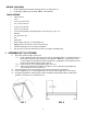
BEFORE YOU BEGIN: 1. 2. Read and follow all instructions/warnings prior to assembly and use. Load rating: 100 lbs. psf live load, 300 lbs. concentrated TOOLS NEEDED: Tape measure Level 9/16” socket or wrench 1/2” socket or wrench 3/16” hex key wrench 5/32” hex key wrench 5/16” masonry drill bit (if installing ramp to concrete porch, steps, etc.
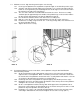
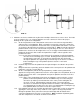
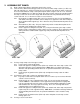
1.5 Platforms over 3 ft. high from the ground require cross bracing. 1.5.1 Insert legs into platform and set platform at required height as described in previous steps. 1.5.2 Separate ends of brace bands until they go around the 1-1/2” square tube and install four bands on each leg with the part containing bolt holes at 90 degrees from each other and in line with the outer edge of the foot (FIG. 3). 1.5.3 The cross brace will come assembled with one bolt in the center.
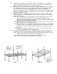
FIG. 5 1.7 FIG. 6 Platforms can also be combined in any direction in multiples of 64-7/16” to create a deck. The initial steps are similar to Sec. 1.5, using two platforms to create a turn-back. Refer to the project drawings for the specific deck configuration. 1.7.1 On the first platform, install a dual platform connector on each of the two legs that will be adjacent to the second platform.
1.7.6 1.7.7 1.7.8 1.7.9 In all locations where there will be no guards or filler sections install the 1-1/2” square x 11” long tube provided through the platform corner pocket and connector until it aligns with the bottom of the connector and tighten all setscrews securely (FIG. 5). At this point there will be one or more legs that extend above the platform deck and will not be used to attach a guard, filler section or corner post.
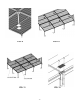
FIG. 9 FIG. 10 FIG. 11 FIG.
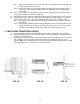
2. ASSEMBLE/SET RAMPS: 2.1 2.2 Begin setting ramps with the uppermost ramps in the system. There are three different bracket types that are used to assemble ramp sections (see FIG. 13a, FIG. 13b and FIG. 13c). All three bracket types are fit into the side rail of the ramp section and are best installed with the ramp section placed upside down using the 5/16-18” x 1.5” hex bolts and washers.
2.5.1 2.6 2.7 2.8 Ramp must be positioned to one side or the other of the platform and should always be positioned to the outside of the turn. 2.5.2 Position the ramp to one side of the platform so that the edge of the transition plate is 4½” from the outer edge of the platform (FIG. 14). Note: The transition plate will be secured later. If the system requires an intermediate “resting” platform, the ramps must be positioned in the center of the platform (see FIG. 28 and FIG. 34).
4. INSTALLING SUPPORT LEGS TO RAMP SECTION(S): 4.1 Install leg support brackets and support legs to ramp section(s) as shown in FIG. 17. Note: Ramp support legs should extend at least 1” past the support tube bracket but no more than 20” above the walking surface of the ramp (FIG. 18). FIG. 17 FIG. 18 4.2 Beginning at the upper end of the ramp system, insert a support leg into the leg support bracket (FIG. 19) and position the foot pad on the leg so it extends beneath the ramp. 4.
4.13 The lowest ramp run will always begin with a starter section. This section requires the same installation procedure with two exceptions. 4.13.1 There is no end support assembly on the tapered end of the ramp section and, since it rests on the ground, no support leg is required. 4.13.2 Only one transition plate is required at the top of the ramp run. 4.14 Install plugs in the top of all support legs. 4.15 Ramps over 3 ft. high from the ground require cross bracing. 4.15.
5. INSTALLING PLATFORM GUARDS: 5.1 Depending on the system configuration, following are four platform guardrail component options that may be used that may be used in different combinations: Five-foot and six-foot guard sections (FIG. 21a) Guard post (FIG. 21b) Guard filler sections for five-foot and six-foot platforms (FIG. 21c) Guard corner sections for five-foot and six-foot platforms (FIG. 21d) FIG. 21a FIG. 21b FIG. 21c – 13 – FIG.
5.2 There are three basic platform arrangements: turn, turn-back, and straight through. Select appropriate guardrail installation and assemble rails as shown in FIG. 22 through FIG. 28. FIG. 22 5.3 5.4 5.5 5.6 FIG. 23 FIG. 24 If platform turns into a door at the top of the system: 5.3.1 Place one guard post over the support leg extending out of the platform corner pocket, opposite both the door and ramp side (FIG. 22). Do not tighten. Note: Tab brackets should be oriented toward the inside. 5.3.
5.7 If platforms are being used to create a deck the entire outer edge of the deck must be guarded. 5.7.1 Installation of the guards at a corner is the same as turning into a door at the top of the system. Refer to FIG. 22 and FIG. 23. 5.7.2 Installation of the guards in a straight run is similar except that only one guard section & post are needed so the unused tab brackets on the post should be oriented to the outside of the deck & capped (same as FIG. 28). 5.
6. INSTALLING RAMP GUARDS: 6.1 6.2 Ramp guards come in left and right pairs and are not interchangeable from side-to-side. For all ramp sections other than the starter section: 6.1.1 Install the Ramp Guard Post Spacers over the 5/16”-18 studs protruding from the brackets previously installed on the ramp section with the long end of the spacer pointing up (FIG 29). 6.1.2 Attach the ramp guard to the ramp section by positioning the lower holes in the ramp guard posts over the studs. 6.1.
7. INSTALLING HANDRAILS: 7.1 Ramp handrails are supplied in left and right pairs and are not interchangeable. 7.1.1 Starting at the lower end of ramp system, attach first handrail section by aligning holes in the handrail brackets with the holes in the guard vertical posts (FIG. 31). Secure with one 5/16”-18 x 2 1/2” button head bolt, washers and nylock nut (place two washers and nylock nut on outside of ramp). 7.1.2 Repeat on all three handrail brackets per handrail section.
8.2 8.3 At the bottom of the ramp (i.e., ground), install two lower loops into the ends of each handrail (FIG. 34). 8.2.1 Install upper portion of loop to handrail using a 4” joiner. Tighten setscrew enough to hold in place, but leave loose enough to rotate. 8.2.2 Rotate lower portion of loop until it lines up with ramp guard post. Mark center, then drill 5/16” hole through post.
8.4 At a turn platform on the outside, non-turn side (both where a the top of a ramp meets a platform and where a ramp starts at a platform) as shown in FIG. 35: 8.4.1 Use a ring joiner to attach one 5 degree elbow to ramp handrail. 8.4.2 Hold 90 degree elbow in position and mark for trimming. 8.4.3 After trimming, test fit elbow. 8.4.4 When fit is confirmed, install threaded insert into short end of elbow with a hammer. 8.4.5 Connect long side to 5 degree elbow with a ring joiner. 8.4.
8.6 At a turn-back platform on the inside, turn-back side (FIG. 37): 8.6.1 Hold two 90 degree elbows in position and mark for trimming. 8.6.2 After trimming, test fit elbows, handrail brackets and spacers. 8.6.3 Attach long legs of elbows in the middle with a ring joiner, and then attach both elbows to handrail tubes with ring joiners (FIG. 38) 8.6.4 Attach handrail brackets and spacers to guard filler section by drilling 5/16” dia. hole through the filler picket. 8.6.
8.7 At an intermediate turn platform on an inside corner (FIG. 39): 8.7.1 Hold two 90 degree elbows in position with the adjustable elbow and mark for trimming. 8.7.2 After trimming, test fit elbows, handrail brackets and spacers. 8.7.3 Attach long legs of 90 degree elbows to adjustable elbow with ring joiners then attach both elbows to handrail tubes with ring joiners. 8.7.
8.8 When child rails are required, the lower (child) handrails and the various returns and connectors are installed in the same manner as the upper (normal) rail using the lower set of holes provided. Refer to instructions in previous steps. 8.8.1 The upper (adult) handrail is also installed in the same manner except the upper and lower termination loops are not used. These components will be replaced by either an upper or lower dual termination loop (FIG. 41). 8.8.
NOTES: Thank you for choosing Please visit www.ezaccess.com or call 1-800-258-8503 for all your ramp and step needs.
Please visit www.ezaccess.com or call 1-800-258-8503 for all your ramp and step needs. 10257 REV 06-19-13 © EZ-ACCESS®, a division of Homecare Products, Inc. All rights reserved. All text and images contained in this document are proprietary and may not be shared, modified, distributed, reproduced, or reused without the express written permission of EZ-ACCESS.