
Instructions / Assembly

Page | 5
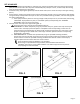
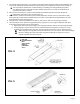
5. For stowage and transportation, or for loading unoccupied mobility equipment with a wider wheelbase, the
ramp can be separated into two halves (FIG. 4) by removing (2 ea.) hinge bolts and nylon locknuts (FIG. 5).
The ramp may be separated for use when loading or unloading unoccupied mobility equipment
only. When the ramp is used with occupied mobility equipment, ensure that the ramp halves are
rejoined as described in ‘STEP 9’.
6. Place the two ramp halves in a position that facilitates the load being centered on each half (FIG. 4).
Always keep ramp loads on the centerlines (FIG. 4).
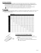
7. Ensure that the surface area of both top lip transition plates fully overlaps a secure, unobstructed, level
landing enough to safely install provided clevis pins or other non-provided anchoring hardware, and rests
firmly against the upper landing (FIG. 3).
8. Securely anchor each ramp half before use (FIG. 4); refer back to ‘STEP 4’ for anchoring procedures.
9. The ramp halves can be rejoined using provided (2 ea.) hinge pins or (2 ea.) original hinge bolts and nylon
locknuts by positioning the ramp as shown (FIG. 5).
a. Align hinges, then insert either a hinge pin or hinge bolt and nylon locknut into each hinge assembly.
b. If using hinge pins, ensure that the pins are closed and that the spring section of the pin is on the
underside (non-treaded side) of the ramp. If using hinge bolts and nylon locknuts, tighten securely.
When hinge pins or hinge bolts and nylon locknuts are not in use, store in one side of the hinge.
Be sure to always rejoin the ramp halves using the provided (2 ea.) hinge pins or (2 ea.)
original hinge bolts and nylon locknuts.
FIG. 4
FIG. 5
USE THIS
CONFIGURATION
WITH
UNOCCUPIED
MOBILITY
EQUIPMENT
ONLY!