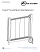
Instructions Passport® Top Landing Gate Hinge Replacement Manufactured in the USA © Homecare Products, Inc. All rights reserved. All text and images contained in this document are proprietary and may not be shared, modified, distributed, reproduced, or reused without the express written permission of EZ-ACCESS®, a division of Homecare Products, Inc.
INSTRUCTIONS Passport® Top Landing Gate Hinge Replacement ATTENTION INSTALLER: • For residential use only! • Read all instructions, labels, and product warnings prior to use. • Please leave this ASSEMBLY MANUAL with the end user. ATTENTION END USER: • Read all instructions, labels, and product warnings prior to use.
1. SYMBOLS, SAFETY, AND WARNINGS 1.1. SYMBOL MEANING WARNING SYMBOL: This symbol may appear in various colors and in conjunction with other symbols. The WARNING symbol indicates that a failure to obey the warning could result in property damage, damage to equipment, serious personal injury, or death, as well as the serious personal injury or death of others. The safety warnings throughout this manual are for the protection of people and property.
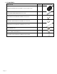
5. KIT CONTENTS: DESCRIPTION QUANTITY HINGE HD STANDARD SELF CLOSING 1.53125" X 3.5625" X 4.75" 2 GATE HINGE CONNECTOR BAR .445" X 1.
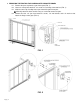
6. REMOVING THE EXISTING TOP LANDING GATE AND GATE HINGES 6.1 Remove the post cap from the gate frame post (FIG. 1). 6.2 Loosen or remove the two 5/16” set screws in each hinge connector bar (FIG. 1). 6.3 Slide the entire Top Landing Gate up and out of the gate frame post. Manually rotate the latch out of the way as needed to remove the gate. 6.4 Remove the four 1/4” pan head machine screws, 1/4”- 20 locknuts and 1/4" washers that attach the hinges to the gate (FIG. 2). FIG. 1 FIG.
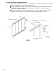
7. INSTALLING THE REPLACEMENT HINGES 7.1 Install hinges using the #10-24 x 3-1/2” pan head machine screws, # 10-24 locknuts and #10 washers included in the hinge replacement kit (FIG. 3). Install the #10-24 x 3-1/2” pan head machine screws with the head of the machine screw on the lift side of the Top Landing Gate, the #10 washers under the head and the #10-24 locknuts in the hinge as shown.
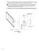
.2 7.3 Attach the replacement hinge connector bars to the replacement hinges using two 1/4”-20 x 5/8” pan head machine screws in the two tapped holes closest to the Top Landing Gate when the hinge connector bars and hinges are oriented as shown (FIG. 4). There are four tapped holes for hinge mounting in the hinge connector bar but only the two closest to the Top Landing Gate are used (depending on which side of the Top Landing Gate the hinges are mounted).
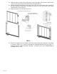
7.4 7.5 7.6 Slide the entire assembly (Top Landing Gate, hinges and hinge connector bars) back into the channel in the gate frame post from which it was removed (FIG. 5). Align the top of the ring magnet on the latch side of the Top Landing Gate with the bottom of the latch mounting clamp plate and tighten all 5/16”-18 x 5/8” set screws in the hinge connector bars securely (FIG. 5). Replace the post cap on the gate frame post. FIG. 5 7.