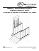
PASSPORT® Vertical Platform Lift (VPL) Installation Manual for Models PL52SP3651, PL72SP3651, PL52TP3860 and PL72TP3860 Manufactured in the USA © 2012-2013 EZ-ACCESS®, a division of Homecare Products, Inc. All rights reserved. All text and images contained in this document are proprietary and may not be shared, modified, distributed, reproduced, or reused without the express written permission of EZ-ACCESS.
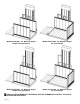
Model PL52SP3651 - 52” Maximum Height Straight Through Platform Model PL52TP3860 - 52” Maximum Height 90° Turn Platform Model PL72SP3651 - 72” Maximum Height Straight Through Platform Model PL72TP3860 - 72” Maximum Height 90° Turn Platform UNLESS NOTED OTHERWISE, THIS MANUAL APPLIES TO MODELS PL52SP3651, PL72SP3651, PL52TP3860 AND PL72TP3860 Page | 2
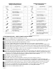
Hardware Bag Contents for Straight Through Platform Hardware Bag Contents for 90° Turn Platform ATTENTION INSTALLER – VERIFY PRIOR TO INSTALLATION: Check for shipping damage immediately upon receipt. Note any freight damage on freight bill while driver is still present. In most cases, freight damage claims will not be allowed unless noted on the freight bill. Pictures of damage before the unit is unpacked can be very helpful. Contact shipper right away with any freight damage concerns.
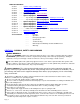
TABLE OF CONTENTS Section 1 - - - - Symbols, Safety and Warnings Section 2 - - - - Labeling and Dealer Contact Information Section 3 - - - - Optional Equipment Notice Section 4 - - - - Assembling the VPL Section 5 - - - - Optional Equipment - Wireless Remote Section 6 - - - - Optional Equipment - Top Landing Gate Section 7 - - - - - - - Top Landing Gate Optional Equipment - Pathway Connector Kit Section 8 - - - - - - - Top Landing Gate Optional Equipment - Deck Connector Kit Section 9 - - - - Optional Equip
Observe and avoid all pinch points. Whenever not actively using the VPL, turn keyed power switch to “OFF” position and remove key. Always unplug VPL from electrical outlet before cleaning. Only plug VPL back in when area around VPL is dry. Never operate VPL with damaged electrical wires, cords, or plugs. The AC electrical plug on this VPL is grounded and intended to be used only with a properly grounded AC outlet. Do not remove ground pin from AC power cord.
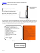
SECTION 2 – LABELING AND DEALER CONTACT INFORMATION Assure all labels are present and legible. VPL Safety labels come pre-installed. Each VPL should have labels positioned on the VPL as illustrated in the image to the right. The labels shown at right are for illustrative purposes only. Labeling on your particular VPL may differ in color, boarders, size, and content. FIG. 2.1 FIG. 2.2 represents a typical VPL Serial Number Label. Assure the VPL Serial Number Label is present and legible on each VPL. FIG.
DEALER CONTACT Contact dealer with questions and for additional information. DEALER NAME: ADDRESS: TELEPHONE: INTERNET: If you need additional assistance, please or call one of the numbers below. Customer Service: 1-800-451-1903 Technical Support: 1-800-332-1381 Internet: www.ezaccess.com. SECTION 3 - OPTIONAL EQUIPMENT NOTICE VPL OPTIONS ARE SOLD SEPARATELY. Options do not come with a Standard VPL, options must be ordered separately.
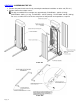
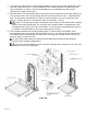
SECTION 4 - ASSEMBLING THE VPL 1. Remove the power head cover first by removing the two button head bolts on either end (FIG. 4.1). 2. Remove front and rear tower covers. The fully assembled VPL net weights are approximately PL52SP3651 - 384 lbs (175 kg), PL52TP3860 - 376 lbs (171 kg), PL72SP3651 - 415 lbs (189 kg), PL72TP3860 - 407 lbs (185 kg). For ease, assemble VPL a few inches away from its final position and reposition as required. FIG. 4.1 FIG. 4.
3. The guard ramp activating bar is shipped with the platform. Locate the guard ramp activating bar splice connector and the 5/16”-18 x 1” long assembly bolts in the hardware bag then assemble the guard ramp activating bar as shown in FIG. 4.2. Do not tighten the assembly bolts fully until after the activating bar is attached to the tower. 4.
6. Locate the wiring connector protruding from the back of the platform and attach to the corresponding connector on carriage (FIG. 4.4). If installing a 90° Turn Platform, skip to Step 13 after connecting platform plug. FIG. 4.4 7. Locate the guard ramp (included in the box with the platform), the guard ramp pivot plates, the 1/4”-20 x 1/2” pivot plate attachment bolts and guard ramp spacers (included in the hardware bag) then slide the pivot plates and spacers over the ramp torque tubes as shown (FIG. 4.
8. Position the guard ramp with pivot plates on the entry side of the platform and secure both pivot plates to the platform with the 1/4”-20 x 1/2” pivot plate attachment bolts (FIG. 4.5). 9. Install the pivot arm assembly (included in the box with the platform) by first locating the 5/16”-18 x 2” hex bolt and locknut included in the hardware bag (FIG. 4.6). a.
FIG. 4.7 11. FIG. 4.8 Install control box mounting frame to rear guard wall by first removing nuts and bolts from control box mounting frame posts (FIG. 4.9). a. Install the mounting frame between the guard wall and tower with the nuts and bolts oriented as shown and tightened securely. FIG. 4.
12. 13. 14. The control box is secured to inside of tower with zip ties. Locate and cut the zip ties to free the control box (FIG. 4.9). a. Remove fasteners securing mounting channels to control box. b. Position control box into the mounting frame as shown and reinstall the mounting channels using the fasteners removed in the previous step. c. Check to make sure that the control box is free to slide entire length of mounting frame.
15. 16. 17. Install the Guard Ramp by first inserting the outer torque tube into the hole in the welded pivot plate assembly. Then install the pivot plate (found in the hardware bag) over the torque tube on the opposite side and attach to the platform in the orientation shown using the four 1/4”-20 x 1/2” pivot plate attachment bolts (FIG. 4.11). Complete Step 9 of this section, installing the pivot arm assembly, before proceeding with guard wall installation.
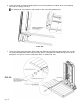
18. 19. Page | 15 The side guard wall will come with its post installed on one side. If the post is not on the side needed for the smooth side to be installed toward the inside of the platform, disassemble the post from the guard wall and reinstall on the opposite side before proceeding. Install the side guard wall with the smooth side toward the inside of the platform as shown in FIG. 4.13. a.
CONFIRM BASIC VPL OPERATION 20. The batteries are fully charged when VPL is shipped. The batteries will maintain their charge for approximately two months under normal conditions. 21. The VPL can now be operated to confirm basic function. Do not operate the VPL while occupied until it is anchored in place. 22. 23. Since the cover panels have not been reinstalled, the lift mechanism will still be exposed at this point.
FIG. 4.15 FIG. 4.14 32. 33. Turn the keyed master switch to the Power “OFF” position, remove key and disconnect VPL from AC power. Reinstall the back cover panel at this time. FIG. 4.15A THE VPL IS NOW READY TO SET IN PLACE - VPL PLACEMENT AND INSTALLATION: IF USING THE VPL WITH A TOP LANDING GATE, PROCEED TO THE TOP LANDING GATE INSTALLATION SECTION PRIOR TO PLACING AND INSTALLING THE VPL. 34. 35. 36. Position the VPL in its approximate final position.
37. 38. 39. Check for adequate running clearances. The platform must be able to travel up and down and the guard ramp must be able to fold and unfold without interference or obstruction. Shim VPL legs as needed to fine tune level. There is a one degree (1°) preload angle built into the VPL platform. Level the VPL using the tower as plumb reference not the platform surface.
45. 46. 47. 48. 49. 50. 51. 52. Page | 19 Locate the limit switch trigger on the upper right inside of the tower side. Place a mark on the tower side aligned with one of the flat head adjustment screws on the limit trigger (FIG. 4.16). Measures down from the mark on the tower side by the same dimension recorded in the previous step and mark the tower at this point. Loosen the two flat head adjustment screws in the limit switch trigger until the trigger moves but do not remove them completely.
SECTION 5 - OPTIONAL EQUIPMENT - WIRELESS REMOTE The Wireless Remote transmitter FOB allows remote operation of the VPL, from a suitable location. The Wireless Remote option can be used in conjunction with the Call/Send Control option. Additional FOB transmitters are available. Multiple FOB transmitters allow VPL operation from various locations, for instance from a dry warm vehicle or from the comfort of your home.
FIG. 5.3 FIG. 5.4 With the receiver properly grounded and secured, the VPL power (both AC and DC) disconnected you will now install the antenna. First, drop the antenna cable down through the cable access port on the VPL FIG. 5.6. FIG. 5.5 Location of Dual Lock, on the underside of the antenna. FIG. 5.5 FIG. 5.7 Next, locate the Splitter FIG. 5.9 Page | 21 FIG. 5.6 FIG. 5.
FIG. 5.9 FIG. 5.10 Peel protective adhesive cover off of dual lock on antenna. FIG. 5.5. Press to stick the dual lock, with antenna, in the location shown in FIG. 5.6. Assure any excess antenna cable is neatly and securely stowed away from all VPL moving parts! Always assure area around VPL is clear before activating the VPL by wireless remote, remote, or push button.
SECTION 6 - OPTIONAL EQUIPMENT – TOP LANDING GATE Never use the Top Landing Gate for uses other than its intended function. Do not modify the Top Landing Gate and latching mechanism. Do not operate the Top Landing Gate latch manually while the VPL is in operation. Never block the Top Landing Gate open or closed. Keep the area around the Top Landing Gate free of debris. Do not play on or around the Top Landing Gate or attach foreign objects to the Top Landing Gate.
INSTALLATION: FIG. 6.1A FIG. 6.
3. The area between the ground and the porch or deck where the VPL Platform will travel must be closed. Consult local building codes and close this area as required. 4. Install the VPL as described elsewhere in the manual.
FIG. 6.3 FIG. 6.
8. Before connecting the Top Landing Gate cord, the VPL Platform must be set at the upper landing level. Proceed with Steps 33 through 51 in Section 4 if not already complete. Connect the Top Landing Gate cord to VPL by first removing rear cover. There will be a cord with a 4-pin connector inside the tower located in the area where the power cord exits the tower. Bring this cord out of the tower and remove the Top Landing Gate jumper plug from the connector.
FIG. 6.
SECTION 7 - TOP LANDING GATE OPTIONAL EQUIPMENT - PATHWAY CONNECTOR KIT The Pathway Connector Kit, pictured on the right, is an option designed to quickly and easily connect a Top Landing Gate to a Pathway platform handrail. FIG. 7.1 INSTALLATION: 1. The Pathway Connector Kit connects a gate post to a platform handrail post. It includes two 1-1/2” diameter handrail tubes, two connector plates, two clamp plates, and the needed hardware (FIG. 7.1).
5. Install the two 5/16”-18 x 4-1/2” long hex bolts through the sill and the platform side rail then secure with the lock nuts and washers provided. 6. Install the four 1/4” self-drilling screws through the sill and into platform walking surface. 7. Remove the post cap from the gate post where the connector will be installed. 8. Assemble one of the handrail tubes to a connector plate using two #10 x 1” long self-tapping hex washer head screws. 9.
SECTION 8 - TOP LANDING GATE OPTIONAL EQUIPMENT - DECK CONNECTOR KIT FIG. 8.1 INSTALLATION: 1. The Deck Connector Kit can be used to tie the Top Landing Gate post to handrails or posts on an existing porch or deck. Each Deck Connector Kit includes two clamp plates, two angle connectors and attachment hardware (FIG. 8.2). The figure only shows one of many possible orientations of the angle connector.
FIG. 8.2 2. Assemble the two 5/16”-18 x 3/4” long button head socket clamp screws through the slots in one leg of the angle connector and into the tapped holes in the clamp plate. The angle connector is symmetric, but do not tighten fully at this time. 3. Remove the post cap and slide the clamp plate into the one of the three channels in the “back” side of the Top Landing Gate post closest to the rail or post where the connection will be made. The angle connector should be on the outside of the post. 4.
SECTION 9 - OPTIONAL EQUIPMENT - PLATFORM SAFETY RAIL The Platform Safety Rail is a required to be installed and used if anyone will be standing on the VPL. When properly installed and used, the Platform Safety Rail option is designed exclusively for the purpose of providing additional personal stability while standing on the VPL. The Platform Safety Rail, pictured at left, is required to be used by anyone standing on the VPL. FIG. 9.1 BEFORE YOU START: 1.
INSTALLATION: For a Straight Platform, measure 3/4” in from the end of one guard wall post and make a mark. Now measure 2-1/2” down from the top of the guard wall post (excluding the plug) and mark. Find the location where the two marks cross. Mark a location on the other guard wall post 2-1/2” down from the top of the guard wall post (excluding the plug) and 48-5/8” away from where the two marks cross on the opposite post. Drill 3/8” diameter holes through both posts at the marked locations (FIG. 9.3A).
2. Install a round threaded insert into one end of each 1-1/2” diameter x 1-1/4” long tube. Use a rubber mallet to make sure the threaded inserts seat fully into the tubes. 3. Hold one 1-1/2” diameter x 1-1/4” long tube with the threaded insert to the inside of the guard wall (the tube will be oriented toward the guard wall post or top rail and the insert will be oriented toward the other side of the platform).
5. Install the elbow halves with the threaded holes onto the portion of the 5/16”-18 x 3” long hex cap screw which extends past the threaded inserts (shown in FIG. 9.4) and tighten securely. After tightening, the rounded side of the elbow halves should be on the bottom facing the platform.
SECTION 10 - OPTIONAL EQUIPMENT - PLATFORM SAFETY PAN WEATHER GUARD The Platform Safety Pan Weather Guard option, pictured to the right, is made of durable EPDM materials and installs quickly by simply clipping onto the Safety Pan. FIG. 10.1 FIG. 10.2 INSTALLATION: 1. Begin at the rear (closest to the lift) and adjacent to one of the outer carriage arms (FIG. 10.2). 2.
SECTION 11 - OPTIONAL EQUIPMENT - INTERLOCK Refer to the Porta Electric Door Lock (6-position) Installation instructions that came with your Porta Electric Door Lock for Interlock A VPL altered to operate with an Interlock, will not operate correctly if electrically connected to a Top Landing Gate. When using an Interlock, the door must swing away from the lift regardless of where the hinges are located. Direction of door swing must be specified at the time you place your order for the optional Interlock.
INTERLOCK ELECTRICAL CONNECTIONS: Terminal 1 Terminal 2 Terminal 3 Terminal 4 Terminal 5 Terminal 6 Unused Unused White Black Green Red A = White B = Green C = Black D = Red FIG. 11.3 FIG. 11.4 INSTALLATION PREPARATION: Strip the 18/4 SOOW cord to expose ½” of copper conductor (see FIG. 11.2 and 11.5). Remove the cover from the Porta Electric EMDL 06 door interlock and connect the wires from the SOOW cord as shown in FIG. 11.3. INSTALLATION: 1.
8. Route the red wire (attached to yellow fuse wire in FIG. 11.6) down through the cable access port (FIG. 5.6) and run parallel to the AC power cord down right side of lift tower behind wire hold-downs. (FIG. 5.7, 11.6). String red wire down to match the length of the other two plugs (FIG. 11.7). FIG. 11.7 FIG. 11.8 FIG. 11.8a (Only use jumper without gate) 9. Locate the 4-pin female connector on end of the rainbow ribbon cable near base of tower and remove the gate bypass jumper (FIG. 11.7).
FIG. 11.11 FIG. 11.12 12. Remove 1/4” nut & bolt attaching purple ground wire to upper left gusset on carriage. Slide 1/4” ring terminal on other end of 16” black wire over bolt and reassemble so both purple and black wires are grounded to carriage. (FIG. 11.11). 13. Secure the added wires to existing wires with the zip ties provided. Cut excess material from zip ties as needed. (FIG. 11.12) 14. Reinstall the front and rear cover panels on lift tower. 15. Reinstall the rear platform guard wall. 16.
SECTION 12 - OPTIONAL EQUIPMENT - CALL/SEND CONTROL Multiple Call/Send Controls can be used with the VPL. This allows you to “call” the platform from multiple locations. (FIG. 12.1) From the bottom of the stairs, or landing; simply press the DOWN button and the platform descends. From the top landing, deck, or porch; simply press the UP button and the platform ascends. FIG. 12.1 INSTALLATION: 1. 2. 3. 4. Connect the Call/Send Control cord to VPL by first removing rear cover.
SECTION 13 - OPTIONAL EQUIPMENT - CALL/SEND CONTROL MOUNTING KIT The Call/Send Control Mounting Kit (FIG. 13.1) option contains the necessary hardware to quickly attach your Call/Send Control of your Top Landing Gate post. Multiple Call/Send Controls can be used with your VPL. Please contact your dealer if you are interested in this, or any other option. Or call 1-800-451-190 3, or visit us online at www.ezaccess.com. FIG. 13.
2. 3. 4. 5. 6. 7. 8. 9. Assemble the two mounting bars to the Call/Send Control using four #10-24 x 3/4” long button head socket cap screws and nylon locking nuts as shown in FIG. 13.2. Assemble the bars in such a manner that the larger hole is on the gate side when mounted to the same post which contains the latching mechanism.
GREASING THE HI-LEAD SCREW: 1. The Hi-Lead® Screw which drives the lift platform up and down must be lubricated at minimum once per ® year or more frequently if the VPL is used in extremely hot or cold locations. Use Chevron Ulti-plex Synthetic Grease EP, NLGI Grade 1.5, or equivalent. (FIG. 14.1) Failure to use the correct grease and or keep the Hi-Lead® Screw properly lubricated can cause equipment failure and will void the warranty. 2.
SECTION 15 – ELECTRICAL DRAWINGS Page | 46