
Instructions / Assembly
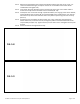

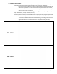


Table Of Contents
- 1. BASIC SYSTEM COMPONENTS
- 2. PLATFORMS
- 2.1. INSTALL PLATFORMS
- 2.2. INSTALL SUPPORT TUBES AND FEET, THEN ADJUST PLATFORM HEIGHT
- 2.3. CONNECT TWO PLATFORMS TOGETHER
- 2.4. 45-DEGREE ANGLE PLATFORM
- 2.5. 8’ X 5’ TURN BACK PLATFORM
- 2.6. LOW PROFILE PLATFORM
- 2.7. INSTALL UNIVERSAL ANGLE BRACE – PLATFORMS
- 2.8. INSTALL UNIVERSAL CROSS BRACE
- 3.1. CONNECT RAMP SECTIONS
- 3.2. INSTALL RAMPS ON PLATFORMS
- 3.3. ATTACH SUPPORT LEG BRACKETS AND LEGS TO RAMPS
- 3.4. INSTALL UNIVERSAL ANGLE BRACE - RAMPS
- 3.5. INSTALL GROUND TRANSITION RAMP
- 3.6. INSTALL A SINGLE RAMP RUN TO AN EXISTING STRUCTURE
- 3.7. ANCHOR RAMP UPPER TRANSITION
- 3.8. ANGLE RAMPS WITH RESPECT TO PLATFORMS, PORCHES, OR DECKS
- 4.1. RAMP WITHOUT HANDRAILS
- 4.2. RAMP HANDRAILS
- 4.3. ASSEMBLE STANDARD PLATFORM HANDRAILS
- 4.4. INSTALL STANDARD PLATFORM HANDRAILS
- 4.5. 8’ X 5’ TURN BACK PLATFORM HANDRAILS
- 4.6. 45-DEGREE ANGLE PLATFORM HANDRAILS
- 5.1. If installing a closure on a platform in the “straight” configuration, the 2” x 2” angle post will already be in place; skip to step 5.4
- 5.2. If installing on a platform in the ‘turn’ configuration, install the 2” x 2” angle post not attached to a platform handrail in the open platform corner pocket. Align the bottom of the post with the bottom of the corner pocket and tighten the set ...
- 5.3. Install an angle cap on top of the handrail post (FIG. 5.1). Use construction adhesive to bond the cap in place.
- 5.4. First install the top rail, the rail connecting the ramp handrail to the platform post.
- 5.5. TWO-LINE CLOSURE
- 5.6. VERTICAL PICKET CLOSURE
- 5.7. TWO-LINE TURN BACK CLOSURE
- 6.1. SECURE RAMP TO PLATFORM
- 6.2. INSTALL RAMP HANDRAIL END LOOPS
- 6.3. INSTALL RAMP HANDRAIL END CAPS
- 6.4. INSTALL RAMP CORNER PROTECTORS
- 6.5. TOUCH-UP ARCHITECTURALLY FINISHED HANDRAILS
- 6.6. FINAL CHECKS
- 7.1. RAMP SUPPORT TOP
- 7.2. RAMP LOWER TRANSITION
- 7.3. SINGLE BRIDGE PLATE
- 7.4. LANDING PAD
- 7.5. PLATFORM TIE STRAPS
- 7.6. LIGHTNING GROUND ROD
- 7.7. TIE DOWN
- 7.8. GATE
- 7.9. CONNECT 45-DEGREE ANGLE PLATFORM WITH TWO-LINE RAILS TO STANDARD PLATFORM
- 8.1. PERIODIC MAINTENANCE AND SAFETY

PATHWAY
®
3G Modular Access System Assembly Manual
Page 51 of 75
1
5.4.12. Measure the gap between the long leg of the bracket and the post then cut the 1-1/2” x 2”
curb to the measured length, less 1/8” to account for the threaded inserts which will be
installed after cutting (FIG. 5.8).
5.4.13. Insert 5/16”-18 square threaded inserts into both ends of the curb. Use a rubber mallet or
similar tool to fully seat the threaded inserts as needed (FIG. 5.8).
5.4.14. Install 5/16″-18 x 1″ hex bolts through a 5/16” flat washers, the long leg of the closure bracket,
and the platform post into the 5/16”-18 round threaded inserts installed in the curb. Use the
hole which is 1/2” above the lowermost hole in the platform post to align the curb correctly
(FIG. 5.9).
5.4.15. Unclamp the closure bracket and drive a 5/16”-18 x 1-1/4” self-drilling, self-tapping hex
washer head screw, centered in the slot, through the platform closure bracket and into the
ramp handrail post (FIG. 5.9). Tighten securely but use caution not to overtighten and strip the
threads.
5.4.16. Ensure all fasteners are tightened securely.
FIG. 5.8
FIG. 5.9