VN-QUANTUM IMAGE V IM N -A G E U A Q D IA S L P N T R O P Y U M C E S R O DISPLAY PROCESSOR
Contents VN-QUANTUM User Guide VN-QUANTUM PROCESSOR USER GUIDE Part No. I455GB issue 8 (6 August 2009) Copyright © 2007 Electrosonic Ltd. All rights reserved. No part of this documentation may be reproduced or transmitted in any form or by any means, electronic or mechanical, including photocopying and recording, without the prior written permission of Electrosonic Ltd.
VN-QUANTUM User Guide Contents IMPORTANT SAFETY MARKINGS The following symbols are used on the throughout this User Guide to advise you of important instructions: This symbol warns the presence of a voltage of sufficient magnitude to cause a severe or fatal electric shock. Follow the appropriate instructions carefully to avoid the risk of injury. This symbol indicates an important instruction for the correct and safe installation, operation or maintenance of your VN-QUANTUM PROCESSOR system.
Contents VN-QUANTUM User Guide This page is intentionally left blank.
VN-QUANTUM User Guide Contents Contents Contents .............................................................................. 5 SECTION 1: .......................................................................... 9 Installation & Setup.................................................................................9 Unpacking Procedure................................................................................................. 10 Checking the Supplied Components.....................................
Contents VN-QUANTUM User Guide Connection Example (ES3301-2 Card Frame)....................................................................... 34 Connection Example (ES3302 & 3304 Card Frame) ............................................................. 35 Changing Network Settings (using the VN-QUANTUM Control Panel) ................................. 36 Connecting the Control PC ........................................................................................ 37 Control Port Settings.............
VN-QUANTUM User Guide Contents 2-Channel DVI Input Card (ES3314).......................................................................................... 56 2-Channel Output Card (ES3310).............................................................................................. 56 Card Arrangement...................................................................................................................... 57 SECTION 3: ........................................................................
Contents VN-QUANTUM User Guide Understanding the Capabilities of VN-QUANTUM.................................................... 80 Overview .................................................................................................................................... 80 Example Scenarios .................................................................................................................... 80 Scenario 1 – Maximum number of video sources on a single screen.................................
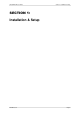
VN-QUANTUM User Guide Section 1: Installation & Setup SECTION 1: Installation & Setup I455GB issue 8 Page 9
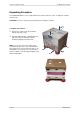
Section 1: Installation & Setup VN-QUANTUM User Guide Unpacking Procedure The VN-QUANTUM Processor, together with various cables and accessories, is shipped in a sturdy wooden crate. CAUTION: The crate is extremely heavy and two-person lifting is required. B To unpack the contents... Remove the eight screws (A) around the bottom edge of the crate. B Using the lifting handles, carefully lift the top half of the crate up and away from the internal packaging and components.
VN-QUANTUM User Guide Section 1: Installation & Setup Checking the Supplied Components Before installing or using the VN-QUANTUM processor please check that all of the following items have been supplied in the shipping crate and have not been damaged during transit ES3301-2 Check List Power Supply Units (PSUs) Two Card Frame PSUs are packed separately for transit and need to be installed into the Card Frame prior to use. See page 13 for installation details.
Section 1: Installation & Setup VN-QUANTUM User Guide ES3302 & ES3304 Check List Mains Power Cords Two IEC 320 (C14) mains power cards are supplied. One is terminated in a 3-pin ‘Edison’ plug (for USA) and the other is unterminated (for Europe and elsewhere). See page 19 for further details on connecting the mains supply. Input Card Breakout Cables These are 26-pin D-type connectors with 12 coaxial flying leads, each approx. 400mm in length and terminated in an inline BNC connector.
VN-QUANTUM User Guide Section 1: Installation & Setup Fitting the Power Supply Units (ES3301-2 only) Open the lower front access panel of the Card Frame. (The panel is secured by a quarter-turn latch). Remove the retaining screw from the lefthand side of both PSU compartments. Insert a PSU fully into each compartment and secure with the retaining screw.
Page 14 (page 20) Connecting the Control PC (page 27) (VN-COMMANDER) Connecting Sources Connecting the Display (page 12) (page 22) (page 24) Connecting a Keyboard, Mouse & Monitor (Network Setup) (page 25) Network 1 Network 2 Connecting to a Network Section 1: Installation & Setup VN-QUANTUM User Guide ES3301-2 Installation Overview I455GB issue 8
I455GB issue 8 (page 27) Connecting the Control PC (VN-COMMANDER) Connecting Video Sources (page 20) (page 12) Connecting the Display (page 22) (page 25) Connecting a Keyboard, Mouse & Monitor (Network Setup) Network 1 Network 2 Connecting to a Network (page 24) VN-QUANTUM User Guide Section 1: Installation & Setup ES3302 & ES3304 Installation Overview Note: The ES3304 VN-QUANTUM CONNECT processor does not support the use of the Media ports (Network interface 1 & 2).
Section 1: Installation & Setup VN-QUANTUM User Guide Installing the Card Frame Choosing a Suitable Location The VN-QUANTUM Processor is primarily designed to be mounted in a 19 inch equipment rack. However, it can be used as a freestanding unit if required. CAUTION However you decide to use the VN-QUANTUM Processor there are certain environmental requirements, detailed on page 17, which must be observed in order to ensure safe and reliable operation.
VN-QUANTUM User Guide Section 1: Installation & Setup Environmental Requirements CAUTION The criteria on this page must be observed for all VN-QUANTUM Processor installations, whether free-standing or rack-mounted. Orientation The VN-QUANTUM Processor must be operated in the horizontal position only. When used freestanding it must be placed on a stable, flat and level surface.
Section 1: Installation & Setup VN-QUANTUM User Guide Rack-mount Requirements CAUTION For rack-mounted installations, the following criteria must be observed (in addition to the Environmental Requirements listed on page 17). Mounting & Support ALWAYS use additional support at the sides or rear of the VN-QUANTUM card frame. For example, by installing a suitable rack-mountable shelf beneath the unit, fixed to both the front and rear rack posts.
VN-QUANTUM User Guide Section 1: Installation & Setup Connecting the Mains Supply Supply Requirements ALWAYS observe the following instructions to ensure safe and reliable operation of the VN-QUANTUM Processor: WARNING: THIS EQUIPMENT MUST BE GROUNDED / EARTHED. NEVER connect the VN-QUANTUM Processor to a power point that does not have a ground or earth connection. ALWAYS ensure that the mains supply voltage is single phase only and is within the permitted range: 110V / 230V AC (13A / 6 A Max.
Section 1: Installation & Setup VN-QUANTUM User Guide Mains Power Cord The VN-QUANTUM Processor is equipped with an IEC320 C14 3-pin (male) type mains connector which requires a power cord fitted with an IEC320 C13 (female) connector. Two power cords are supplied with the VN-QUANTUM Processor, each having a different termination; you must use the lead appropriate for the country of installation: In... Use the... Re-order Code USA and Canada cord fitted with the 3-pin American-style ‘Edison’ plug.
VN-QUANTUM User Guide Section 1: Installation & Setup Fitting a Mains Plug If you are fitting a plug to the unterminated power cord (or replacing an existing plug), the plug MUST: • • • • be rated for use with mains voltage be equipped with a grounding pin/connection comply with any applicable National or Local electrical regulations. be fitted with a correctly rated fuse (applicable to UK-style plugs only – see page 22.
Section 1: Installation & Setup VN-QUANTUM User Guide External Supply Protection The mains power cord must be protected from overload by an external fuse or circuit breaker. Fused Plugs (UK-style) If the power cord is fitted with a UK-style BS1363 3-pin plug (i.e. with provision for an internal fuse), then it must be fitted with a BS1362 ASTA approved 1 inch cartridge fuse rated at 10A/250V.
VN-QUANTUM User Guide Section 1: Installation & Setup Power-up Test (ES3301-2 only) Ensure that the Card Frame is connected to the mains supply. Ensure that all ventilation grilles are free from obstruction. Open the lower front access panel (secured by a quarter-turn latch). Move both PSU switches to the ON (1) position. Move the main POWER switch to the ON (1) position. Check for the following: o The main POWER indicator lights green. o Both PSU indicators light green.
Section 1: Installation & Setup VN-QUANTUM User Guide Connecting Sources Video Sources Analog video sources are connected to the Card Frame via one or more ES3311-2 Input Cards. Each card can accept up to 12 composite (CVBS) or S-Video (YC) sources, and inputs are made via two multi-way connectors at the rear of each card: The upper connector is for composite or S-Video luma (Y); The lower connector is for S-Video chroma (C) only.
VN-QUANTUM User Guide Section 1: Installation & Setup Connection Example ES3311-2 Card ES3311-CA Breakout Cable ES3311-CA Breakout Cable (required for S-Video sources only) DVD PLAYER VIDEO SERVER CAMERA S-VHS PLAYER NOTE: The Y and C outputs of an S-Video source must be connected to the same input number on both cables.
Section 1: Installation & Setup VN-QUANTUM User Guide RGB Graphics & HD Video Sources Analog RGB graphics sources or HD Video sources (in RGB or component YPrPb format) are connected to the Card Frame via one or more ES3312 RGB Input Cards. Each ES3312 card can accept 1 or 2 sources, and inputs are made via two standard 15-pin VGA type connectors at the rear of each card: The upper connector is for Input 1; The lower connector is for Input 2.
VN-QUANTUM User Guide Section 1: Installation & Setup Connection Example ES3312 Card RGB / YPrPb Source RGB / YPrPb Source I455GB issue 8 Page 27
Section 1: Installation & Setup VN-QUANTUM User Guide DVI Sources Digital video or graphics sources are connected to the Card Frame via one or more ES3314 DVI Input Cards. Each ES3314 card can accept 1 or 2 sources, and inputs are made via two standard DVI-D type connectors at the rear of each card: The upper connector is for Input 1; The lower connector is for Input 2.
VN-QUANTUM User Guide Section 1: Installation & Setup Connection Example ES3314 Card DVI Source DVI Source I455GB issue 8 Page 29
Section 1: Installation & Setup VN-QUANTUM User Guide Connecting the Display Display devices are connected to the Card Frame via one or more ES3310 Output Cards. Each ES3310 card has two output channels and these are accessed via two DVD-I connectors at the rear of each card: The upper connector is for output channel 1; The lower connector is for output channel 2. The outputs can be configured (using VN-COMMANDER) to drive either analog or digital devices and at a variety of resolutions.
VN-QUANTUM User Guide Section 1: Installation & Setup Connection / Mapping Examples All of the following display layout examples show channel numbering as seen from the normal viewing position. The first digit is the slot number of the card and the second is the output number. Note that the actual slot numbers may vary between systems, but the general recommendation is to start with the lowest numbered card slot in the top left corner.
Section 1: Installation & Setup VN-QUANTUM User Guide Connecting to a Network The VN-QUANTUM Card Frame has two separate network ports – MEDIA I and MEDIA II. These allow connection to external Ethernet Local Area Networks (LAN) or Wide Area Networks (WAN) in order to access remote VN-GLIMPSE RGB sources or network-based files/media. If your system does not use VN-GLIMPSE sources or network-based content, these ports can be left unconnected. Otherwise, you can use either or both ports as required.
VN-QUANTUM User Guide Section 1: Installation & Setup Connecting a Keyboard, Mouse & Monitor It is only necessary to connect a keyboard, mouse and monitor to the VN-QUANTUM if you need to perform one of the following operations: Change Network Settings Return to Default System Settings Access Service Mode Install New Software VN-QUANTUM only supports PS/2-compatible mice and keyboards. A suitable PS/2 mouse and keyboard is supplied, together with a splitter cable.
Section 1: Installation & Setup VN-QUANTUM User Guide MEDIA I MEDIA II Connection Example (ES3301-2 Card Frame) Page 34 I455GB issue 8
VN-QUANTUM User Guide Section 1: Installation & Setup Connection Example (ES3302 & 3304 Card Frame) PS/2 Splitter Cable I455GB issue 8 Page 35
Section 1: Installation & Setup VN-QUANTUM User Guide Changing Network Settings (using the VN-QUANTUM Control Panel) Ensure that the VN-QUANTUM is powered down. Connect a keyboard, mouse and monitor to the VN-QUANTUM Card Frame (see page 33) Power-up the VN-QUANTUM processor and wait for the VN-QUANTUM logo to appear on the monitor (this will take up to 90 seconds).
VN-QUANTUM User Guide Section 1: Installation & Setup Connecting the Control PC VN-QUANTUM has a dedicated CONTROL port for the connection of a PC or laptop, running VNCOMMANDER application software. Connection between the CONTROL port and the PC or laptop must be made using a CAT5 crossover patch cable (a 5m/16ft cable is supplied). Control Port Settings The VN-QUANTUM is shipped with the CONTROL port set to the following: IP Address Subnet Mask Default Gateway DNS Server WINS Server Name 172.28.232.
Section 1: Installation & Setup VN-QUANTUM User Guide Installing VN-COMMANDER Software IMPORTANT NOTE: VN-QUANTUM requires VN-COMMANDER v1.4 software. No other version of VN-COMMANDER or CT-COMMANDER will work with VN-QUANTUM. The VN-QUANTUM CONNECT processor requires VN-COMMANDER CONNECT control software. No other version of VN-COMMANDER will work with the VN-QUANTUM CONNECT processor.
VN-QUANTUM User Guide Section 2: Hardware Overview SECTION 2: Hardware Overview I455GB issue 8 Page 39
Section 2: Hardware Overview VN-QUANTUM User Guide Introduction This section contains a general description of the VN-QUANTUM hardware and concentrates on giving details of the various hardware components and the location of key physical features. For an overview of VN-QUANTUM functionality, refer to Section 3. Note: The ES3304 VN-QUANTUM CONNECT processor has the same architecture as the ES3302 VN-QUANTUM processor.
VN-QUANTUM User Guide Section 2: Hardware Overview Hardware Block Diagram (ES3301-2 Card Frame) VIDEO SOURCES RGB SOURCES DVI SOURCES ES3312 ES3314 Input Card(s) DISPLAY DEVICES ES3301-2 Card Frame ES3310 Output Card(s) RAPT BUS PCI BUS NETWORK INTERFACE 1 NETWORK INTERFACE 2 SINGLE BOARD COMPUTER FLASH MEMORY DRIVE SCALER NETWORK INTERFACE 3 CPU / Operating System MEDIA NETWORK DATA NETWORK KEYBOARD / MOUSE CONTROL (for low-level setup only) RGB SOURCES (VN-GLIMPSE) I455GB issue 8 CONT
Section 2: Hardware Overview VN-QUANTUM User Guide Hardware Block Diagram (ES3302 & 3304 Card Frame) VIDEO SOURCES RGB SOURCES DVI SOURCES ES3312 ES3314 Input Card(s) DISPLAY DEVICES ES3302 Card Frame ES3310 Output Card(s) RAPT BUS PCI BUS NETWORK INTERFACE 1 NETWORK INTERFACE 2 SINGLE BOARD COMPUTER IDE DISK DRIVE SCALER NETWORK INTERFACE 3 CPU / Operating System MEDIA NETWORK DATA NETWORK KEYBOARD / MOUSE CONTROL (for low-level setup only) RGB SOURCES (VN-GLIMPSE) CONTROL PC NETWORK C
VN-QUANTUM User Guide Section 2: Hardware Overview 15-slot Card Frame (ES3301-2) Front Panel Features Thumb Screws for Upper Access Panel Status Indicators Latch for Lower Access Panel Cooling Fans Flash Drive Power On/Off Button O/S Reset Button Power Supply Units HINT: For full technical details on the Card Frame see page 91.
Section 2: Hardware Overview VN-QUANTUM User Guide Status Indicators POWER: Lit green when the mains power supply is OK. Lit red if one of the PSUs has failed. DATA: Flashes when data is being written to, or read from, the flash drive. Lower Access Panel & Latch A fold-down access panel providing access to the following components: Power On/Off Button System Reset Button Flash Drive Bay Power Supply Units • • • • The access panel is normally secured in the closed position by a quarter-turn latch.
VN-QUANTUM User Guide Section 2: Hardware Overview Power Supply Units (PSU) The Card Frame is fitted with two separate PSUs which operate in a redundant PSU configuration. Both PSUs must be fitted and powered ON at all times during normal operation. Should either of the PSUs fail an alarm will sound and the POWER indicator on the front panel will turn red. Both PSUs must be installed and powered at all times.
Section 2: Hardware Overview VN-QUANTUM User Guide Internal Components CPU / Operating System System control is achieved by a single board computer (SBC) running an embedded version of Windows XP with RTX real time extension. This, coupled with the solid-state Flash storage of system data, ensures maximum integrity and reliability of the operating system. PCI Bus A standard high-speed PCI bus provides interconnection between all cards. This primarily carries control data, plus local/network source data.
VN-QUANTUM User Guide Section 2: Hardware Overview Rear Panel Features ES3311-2 12-Channel Video Input Cards ES3310 2-Channel Output Cards Card Slot 15 Card Slot 1 Network Ports USB Ports Control Port Monitor Out Card Slot 0 PS/2 Ports (Keyboard/Mouse) Mains Inlet Connector & Latch Mains Inlet Connector & Latch Mains connection to the unit is via this standard IEC 3-pin connector. A latch is provided which hooks over the mains plug to prevent it from becoming accidentally loosened or disconnected.
Section 2: Hardware Overview VN-QUANTUM User Guide Monitor Output A connector for an optional VGA-compatible display device (e.g. a CRT or LCD monitor). This can be used to view internal settings during basic setup, servicing and fault diagnosis procedures. It is not required during normal operation. PS/2 Ports Connectors for an optional PS/2-compatible keyboard and/or mouse. These are required for basic system setup and troubleshooting only. Not otherwise required for normal operation.
VN-QUANTUM User Guide Section 2: Hardware Overview 8-slot Card Frame Front Panel (ES3302) Status Indicators Latch for Access Panel Cooling Fans Removable Hard Disk O/S Reset Button Power On/Off Button HINT: For full technical details on the Card Frame see page 911.
Section 2: Hardware Overview VN-QUANTUM User Guide Front Panel (ES3304 QUANTUM CONNECT) The ES3304 VN-QUANTUM CONNECT frame has the same physical construction as the ES3302 with a different front panels design. Front Panel Features Status Indicators POWER: Lit green when the mains power supply is OK. DATA: Flashes when data is being written to, or read from, the hard disk drive.
VN-QUANTUM User Guide Section 2: Hardware Overview C: for the operating system, and D: for system configuration files and image files. NOTE: This drive is not hot-swappable. Cooling Fans Two integral fans provide forced-air ventilation, drawing air in through the front panel and exhausting via the rear panel. In the event of a fan failure a replacement fan can be easily hot-swapped via the front panel (see page 88).
Section 2: Hardware Overview VN-QUANTUM User Guide Internal Components CPU / Operating System System control is achieved by a single board computer (SBC) running an embedded version of Windows XP with RTX real time extension. PCI Bus A standard high-speed PCI bus provides interconnection between all cards. This primarily carries control data, plus local/network source data.
VN-QUANTUM User Guide Section 2: Hardware Overview Rear Panel Features ES3311-2 12-Channel Video Input Cards Card Slot 1 ES3310 2-Channel Output Cards Card Slot 8 Monitor Out Network Ports Mains Inlet Connector Control Port USB Ports PS/2 Port (Keyboard/Mouse) Mains Inlet Connector Mains connection to the unit is via this standard IEC 3-pin connector.
Section 2: Hardware Overview VN-QUANTUM User Guide Monitor Output A connector for an optional VGA-compatible display device (e.g. a CRT or LCD monitor). This can be used to view internal settings during basic setup, servicing and fault diagnosis procedures. It is not required during normal operation. PS/2 Port A connector for an optional PS/2-compatible keyboard and/or mouse. These are required for basic system setup and troubleshooting only. Not otherwise required for normal operation.
VN-QUANTUM User Guide Section 2: Hardware Overview Input / Output Cards 12-Channel Video Input Card (ES3311-2) The ES3311-2 Input Card allows external analog video sources to be digitized and used by the VN-QUANTUM Processor. Each card has 12 source inputs which can be used with either composite video or s-video sources. Full auto-detection is provided on each input, allowing a wide range of standard source types to be connected without the need for any further configuration.
Section 2: Hardware Overview VN-QUANTUM User Guide 2-Channel DVI Input Card (ES3314) The ES3314 Input Card allows external digital video or graphics sources to be used by the VNQUANTUM Processor. Each ES3314 card has 2 source inputs. Full auto-detection is provided on each input, allowing a wide range of standard source types to be connected without the need for any further configuration.
VN-QUANTUM User Guide Section 2: Hardware Overview Card Arrangement VN-QUANTUM Card Frames are configured to order. Therefore, the precise combination and position of cards will vary from system to system and may not be as illustrated on previous pages. At least one Output Card and one Input Card will be required in all cases but, other than that, any number or mix of Input and Output cards may be used depending on the number of input or output channels required and the number of available slots.
Section 3: Functional Overview VN-QUANTUM User Guide SECTION 3: Functional Overview Page 58 I455GB issue 8
VN-QUANTUM User Guide Section 3: Functional Overview System Overview The diagram below shows an example system application for a VN-QUANTUM Display Processor. In this particular application, a selection of video, RGB and network sources can be displayed on a 4-screen target display. The VN-COMMANDER software application is responsible for controlling the VN-QUANTUM and placing the required sources onto the target display.
Section 3: Functional Overview VN-QUANTUM User Guide External Sources Analog video sources, such as cameras, VHS/DVD players and video servers, are input into the VN-QUANTUM Processor through one or more ES3311-2 Input Cards. Analog RGB graphics or HD Video sources are input into the VN-QUANTUM Processor through one or more ES3312 Input Cards.
VN-QUANTUM User Guide Section 3: Functional Overview Auto-detection of Source Types Full auto-detection is provided on each input, allowing a wide range of standard source types to be connected without the need for any further configuration. However, VN-COMMANDER provides the means to create fixed or custom input modes. NOTE: PAL 60 format is not supported. PAL 60 is commonly output by European VCRs when playing back an NTSC tape.
Section 3: Functional Overview VN-QUANTUM User Guide De-interlacing VN-QUANTUM outputs a progressive scan to the target display. Most sources that will be connected to the Video Input Card will be interlaced scan and need to be converted to a progressive scan (or ‘de-interlaced’. The Video Input Card can use one of two de-interlacing modes: Single Field Interpolation Three Field Interpolation For a full explanation of these modes please see page 76.
VN-QUANTUM User Guide Section 3: Functional Overview 2-Channel RGB Input Card (ES3312) Card Architecture 2 RGB/YPrPb Inputs The following diagram shows the main functional blocks of the ES3312 card and basic data/signal flow through the card: ES3312 RGB Input Card RGB DECODER PROCESSING & DOWN-SCALING CONTROL PCI BUS RAPT BUS Each card can accept 1 or 2 analog RGB graphics sources or HD Video sources (in RGB or component YPrPb format).
Section 3: Functional Overview VN-QUANTUM User Guide De-interlacing VN-QUANTUM outputs a progressive scan to the target display. Most sources that will be connected to the RGB Input Card will be progressive scan and will not require any special processing.
VN-QUANTUM User Guide Section 3: Functional Overview 2-Channel DVI Input Card (ES3314) Card Architecture The following diagram shows the main functional blocks of the ES3314 card and basic data/signal flow through the card: 2 DVI Inputs ES3314 DVI Input Card DVI DECODER PROCESSING & DOWN-SCALING CONTROL PCI BUS RAPT BUS Each card can accept 1 or 2 DVI sources. The maximum number of ES3314 cards that can be installed is limited only by the number of available card slots (see table on page 57).
Section 3: Functional Overview VN-QUANTUM User Guide De-interlacing VN-QUANTUM outputs a progressive scan to the target display. Most sources that will be connected to the DVI Input Card will be progressive scan and will not require any special processing.
VN-QUANTUM User Guide Section 3: Functional Overview Network Sources VN-GLIMPSE RGB Graphics Sources Applications running on remote computers can be ‘captured’ using VN-GLIMPSE. This is ELECTROSONIC’s patented technology for the efficient lossless transportation of RGB computer graphics over a standard IP network.
Section 3: Functional Overview VN-QUANTUM User Guide Image Files VN-QUANTUM can display certain types of image files as ‘sources’ on the target display. Any number of Image file sources can be used simultaneously (subject to available space on the display). File types currently supported include: • • • • Windows Bitmaps (BMP) JPEG Images (JPG) Compuserve Bitmaps (GIF) Portable Network Graphics (PNG) Additional plug-ins may be made available to special order to allow other file types to be displayed.
VN-QUANTUM User Guide Section 3: Functional Overview RAPT Image Bus RAPT (Real-time Asymmetric Packetized Transfer) is a high-speed data bus used exclusively for the transfer of digitized video and RGB source data between Input and Output Card(s). It is also used to carry any VN-GLIMPSE sources to the Output Card(s).
Section 3: Functional Overview VN-QUANTUM User Guide RAPT Bandwidth Management In the unlikely event that the number of sources displayed on the target display exceeds the real-time capacity of the RAPT bus, VN-QUANTUM implements a system of bandwidth management. All sources are processed at the full temporal rate of the system. This is the rate at which the displays run, either 50 or 60Hz. The RAPT bandwidth usage is monitored dynamically.
VN-QUANTUM User Guide Section 3: Functional Overview Target Display The target display can comprise a single screen (using a single output channel) or a larger tiled display comprising two or more screens butted together. Final output from the VN-QUANTUM to the target display is achieved via one or more ES3310 Output Cards.
Section 3: Functional Overview VN-QUANTUM User Guide Source Delivery Sources are delivered to the Output Card either via the RAPT bus or via the PCI bus: VN-QUANTUM SOURCES TARGET DISPLAY Video (PAL/NTSC/SECAM) Composite (CVBS) S-Video (YC) PCI SOURCE LAYER (unlimited source windows) ES3311-2 Video Input Card RAPT SOURCE LAYER (up to 64 source windows per card) Digital Video ES3310 Output Card DVI-D ES3314 DVI Input Card RAPT BUS HD Video PCI BUS ES3312 RGB Input Card Component (YPrPb) Analo
VN-QUANTUM User Guide Section 3: Functional Overview Up-Scaling The on-board scaler provides up-scaling (magnification) of video, RGB and VN-GLIMPSE sources. Independent horizontal and vertical scaling is possible up to 16x native resolution. For example, a source of 720x486 pixels can be scaled up to around 11520x7776 pixels. The scaling engine is built around Electrosonic’s patented convolver technology which ensures that original image detail and quality is maintained at all times.
Section 3: Functional Overview VN-QUANTUM User Guide Understanding the Display Architecture When VN-QUANTUM is controlled by VN-COMMANDER, sources are placed on the display in ‘windows’ which are fully resizable and can be positioned anywhere on the display. NOTE: VN-QUANTUM ‘remembers’ the last display layout in force before being powered-down. Prior to shipping all new VN-QUANTUM systems have a single, full-size window, placed on the display containing a VN-QUANTUM logo design.
VN-QUANTUM User Guide Section 3: Functional Overview Advanced Operating Principles Source Scaling VN-QUANTUM allows video, RGB and DVI sources to be scaled up or down in size by using the scalers on the Input and Output Cards. Down-scaling or ‘minification’ is performed by the Input Card and can be up to 16 times smaller (both horizontally and/or vertically) than the original source.
Section 3: Functional Overview VN-QUANTUM User Guide De-interlacing VN-QUANTUM outputs a progressive scan to the target display. Therefore, incoming interlaced sources are converted to a progressive format using one of two de-interlacing modes: Single Field Interpolation: each field from the interlaced source is transferred separately across the RAPT bus. The ‘missing’ lines from each field are then interpolated by the Output Card to produce a new progressive frame.
VN-QUANTUM User Guide Section 3: Functional Overview Input & Output Card Grouping In a standard configuration all Input and Output Cards are grouped together in the Card Frame. For example: This arrangement allows each video input to be displayed on any (or all) output channels. The maximum number of real-time sources that can be displayed is limited by the capacity of the RAPT (typically 48 full-resolution, full motion video sources).
Section 3: Functional Overview VN-QUANTUM User Guide Control Low-level setup of VN-QUANTUM (e.g. changing network settings) can be achieved using either the VN-QUANTUM Control Panel application or the VN-QUANTUM Administrator running on a separate PC. All high-level setup (e.g. display and source configuration) and positioning of source windows on the target display is achieved using the VN-COMMANDER application. VN-QUANTUM Control Panel This is an application that runs on the VN-QUANTUM processor.
VN-QUANTUM User Guide Section 3: Functional Overview Remote Control of VN-COMMANDER VN-COMMANDER can be remotely controlled using RS-232 serial strings. These allow full control of scene selection as well as window size, positioning and contents. Control strings may be generated by various means. In addition, VN-COMMANDER can be controlled by an automation client. This allows customized user interfaces to be created for specific applications.
Section 3: Functional Overview VN-QUANTUM User Guide Understanding the Capabilities of VN-QUANTUM Overview VN-QUANTUM is a highly versatile system capable of displaying a large number of sources in realtime on a target display.
VN-QUANTUM User Guide Section 3: Functional Overview Scenario 1 – Maximum number of video sources on a single screen Screen Layout A single UXGA display device is used to display 64 video source windows arranged as an 8x8 array. The total display size is 1600x1200 pixels, making each window 200x150 pixels. Because each window is smaller than the native source resolution, each source is scaled down to the required size by the Input Card.
Section 3: Functional Overview VN-QUANTUM User Guide Scenario 2 – Maximum number of Full Res video sources on a tiled display Screen Layout 12 UXGA display devices are used to create a 4x3 tiled display. 48 video source windows are arranged as an 8x6 array. The total display size is 6400x3600 pixels, making each window 800x600 pixels.
VN-QUANTUM User Guide Section 3: Functional Overview Scenario 3 – Maximum number of video sources on a tiled display Screen Layout 6 UXGA display devices are used to create a 3x2 tiled display. 144 video source windows are arranged as a 12x12 array. The total display size is 4800x2400 pixels, making each window around 133x100 pixels. Because each window is smaller than the native source resolution, each source is scaled down to the required size by the Input Card.
Section 3: Functional Overview VN-QUANTUM User Guide Scenario 4 – Maximum number of video sources on the largest display Screen Layout 8 UXGA display devices are used to create a 4x2 tiled display. 132 video source windows are arranged as a 16x8 array. The total display size is 6400x2400 pixels, making each window 400x300 pixels. Because each window is smaller than the native source resolution, each source is scaled down to the required size by the Input Card.
VN-QUANTUM User Guide Section 3: Functional Overview This page is intentionally left blank.
Section 4: Maintenance VN-QUANTUM User Guide SECTION 4: Maintenance Page 86 I455GB issue 8
VN-QUANTUM User Guide Section 4: Maintenance Component Replacement Procedures Removing and Replacing a PSU (ES3301-2 only) In the event of a PSU failure, an audible alarm will be triggered and the POWER indicator will show red. Also the normally-lit status indicator on the faulty PSU will be extinguished. The alarm will continue to sound until the fault condition has been removed.
Section 4: Maintenance VN-QUANTUM User Guide Removing and Replacing a Cooling Fan Always use an Electrosonic Replacement Fan, Part No. ES3301-F or ES3302-F. Remove the upper access panel by unscrewing the two thumbscrews. Unplug the supply lead to the faulty fan. Remove the single retaining screw from above the fan. Supply Plug Retaining Screw Withdraw the fan by tilting the top forward and lifting away.
VN-QUANTUM User Guide Section 4: Maintenance This page is intentionally left blank.
Section 5: Technical Data VN-QUANTUM User Guide SECTION 5: Technical Data Page 90 I455GB issue 8
VN-QUANTUM User Guide Section 5: Technical Data ES3301-2 15-Slot Card Frame Mechanical Data Overall Dimensions: Weight: 23.5 kg (51.8 lbs) without cards. Power Supply Supply Voltage: Supply Frequency: Max. Power Consumption: Inlet Connector: Mating Connector: 110 – 230V A.C. nominal (90 – 264V A.C. absolute). 50 – 60 Hz nominal (47 – 63 Hz absolute). 300 – 500W IEC320 (C14). IEC320 (C13); suitable 2m (6ft) cable supplied. WARNING: THIS EQUIPMENT MUST BE GROUNDED/EARTHED.
Section 5: Technical Data VN-QUANTUM User Guide Operating System Software: CPU: Memory: Data Transport: Video Transport: Data Storage: Page 92 ® Windows XP Embedded ® + Ardence (VenturCom) RTX Real Time Extension ® 1.8GHz Pentium M. 1GB DDR RAM 64-bit 66/33MHz PCI Bus 10Gbps RAPT Bus Dual-Slot Compact Flash Drive. Top Slot: Operating System. Bottom Slot: System Backup or Image File Storage.
VN-QUANTUM User Guide Section 5: Technical Data ES3302 & 3304 8-Slot Card Frame Mechanical Data Overall Dimensions: FRONT VIEW A B C TOP VIEW DE Weight: A B C D E mm inches 178 7.0 483 19.0 433 17.1 530 20.9 490 19.3 15 kg (33 lbs) without cards. Power Supply Supply Voltage: Supply Frequency: Max. Power Consumption: Inlet Connector: Mating Connector: 110 – 230V A.C. nominal (90 – 264V A.C. absolute). 50 – 60 Hz nominal (47 – 63 Hz absolute). 500W IEC320 (C14).
Section 5: Technical Data VN-QUANTUM User Guide Operating System Software: CPU: Memory: Data Transport: Video Transport: Data Storage: Page 94 ® Windows XP Embedded ® + Ardence (VenturCom) RTX Real Time Extension ® 2.8GHz Pentium IV. 1GB DDR RAM 32-bit PCI Bus 10Gbps RAPT Bus Single 40MB IDE Drive in removable caddy (not hot swap) partitioned as. C: for the operating system. D: for configuration and image file storage.
VN-QUANTUM User Guide Section 5: Technical Data Control Inputs/Outputs The following control input/output connectors appear on the ES3301-2 and ES3302 / 3304 Card Frames. CONTROL Port Function: Connector Type: Pin-out Details: Connection to a VN-COMMANDER control PC. Shielded RJ-45 Socket. Pin 1 2 3 4 Mating Connector: Recommended Cable: Max.
Section 5: Technical Data VN-QUANTUM User Guide Keyboard/Mouse (PS/2 Port) Function: Connector Type: Pin-out Details: Connection for optional PS/2-compatible keyboard and/or mouse – not required during normal usage. Only required during commissioning and troubleshooting using the integral Quantum Control Panel facility. A splitter cable/adapter is required to connect both a mouse and keyboard simultaneously to the ES3302 Card Frame. NOTE: PS/2 does not support hot-plugging.
VN-QUANTUM User Guide Section 5: Technical Data USB Port Function: Connector Type: Pin-out Details: Mating Connector: Recommended Cable: Maximum Cable Length: Comms Standard: I455GB issue 8 Optional storage device or data upload/download – not required for normal operation. USB A Socket. 1=+5V 2=Data – 3=Data + 4=Ground USB A Plug with metal cover. USB Cable. 5 metres (16 feet). USB 2.
Section 5: Technical Data VN-QUANTUM User Guide ES3310 Output Card Function: Card Weight: Connector Type: Pin-out Details: Final composited video output to the target display. Sources can be derived from Video (via ES3311-2 Input Card), RGB and DVI Graphics, VN-GLIMPSE and Image Files. Provides up-scaling (magnification) of sources. Two output channels are provided per card. 0.29 kg (0.63 lb). DVI-I (female).
VN-QUANTUM User Guide Section 5: Technical Data ES3311-2 Video Input Card Function: Card Weight: Connector Type: Pin-out Details: Input for up to 12 composite video (CVBS) and/or s-video (YC) sources. Provides digitization and down-scaling of sources. Two connectors are provided – one for composite or S-Video luma (Y) signals, the other for S-Video chroma (C) signals. A suitable breakout cable is supplied (ES3311-CA, see page 100). Full source auto-detection is provided. 0.26 kg (0.56 lb).
Section 5: Technical Data VN-QUANTUM User Guide ES3311-CA Breakout Cable (for video input card) Function: Connector Type: Mating Connector: Lead Length: Page 100 A breakout/splitter cable for use with the ES3311-2 Video Input Card. Provides a separate flying lead with inline connector for each of the 12 input channels. The connectors are labeled 1 thru 12. BNC (female). BNC (male). 400mm nominal.
VN-QUANTUM User Guide Section 5: Technical Data ES3312 RGB Input Card Function: Card Weight: Connector Type: Pin-out Details: Input for 1 or 2 analog RGB or component YPrPb sources. Provides digitization and down-scaling of sources. Full source auto-detection is provided. 0.26 kg (0.56 lb). 2 x 15-pin High Density D-type (female).
Section 5: Technical Data VN-QUANTUM User Guide ES3314 DVI Input Card Function: Card Weight: Connector Type: Pin-out Details: Input for 1 or 2 digital video or graphics sources. Provides downscaling of sources as required. Full source auto-detection is provided. 0.26 kg (0.56 lb). 2 x DVI-D (female).
VN-QUANTUM User Guide Appendix A: Guide to IP Addressing APPENDIX A: Guide to IP Addressing I455GB issue 8 Page 103
Appendix A: Guide to IP Addressing VN-QUANTUM User Guide What is an IP Address? A full explanation of IP addressing is beyond the scope of this user guide. However the following details will provide you with enough information to get started. An IP Address is a 32-bit binary number that is used to identify each device on an Ethernet network. This number is usually represented by four decimal numbers (each in the range 0 to 255) separated by dots, e.g. 198.123.34.240.
VN-QUANTUM User Guide Appendix A: Guide to IP Addressing Choosing IP Addresses If your VN Processor(s) and control PC are directly connected or connected via their own independent network, then follow the guidelines below for choosing your IP Address(es). However, if you intend connecting your VN Processor(s) and control PC to an existing network, you will need to advise the network administrator and ask them to allocate suitable addresses to you.
Appendix A: Guide to IP Addressing VN-QUANTUM User Guide Subnet Mask The Subnet Mask is another 32-bit binary number that is used to ‘mask’ certain bits of the IP Address. This provides a method of extending the number of network options for a given IP Address. It works by allowing part of the host identifier to be used as a ‘subnet identifier’. Any further explanation of this facility is not relevant to VISION NETWORK. However, it is important that you set the correct value for the Subnet Mask.
VN-QUANTUM User Guide Appendix A: Guide to IP Addressing Using the ‘Ping’ Utility to Test Communications You can test for communications between a Windows computer and another device on the same network by using the Windows Ping utility. From the Windows Desktop of the computer, click on the Start button, and select Run from the pop-up menu. The Run dialog box will appear. In the Open box, type in the following command: ping xxx.xxx.xxx.xxx –t where xxx.xxx.xxx.xxx is the IP Address of the device (e.g.
Appendix A: Guide to IP Addressing VN-QUANTUM User Guide This page is intentionally left blank.
rh=J=içåÇçå qÉäW=HQQ=NPOO=OOO=ONN==c~ñW=HQQ=NPOO=OUO=OUO bJã~áäW=áåÑçêã~íáçå]ÉäÉÅíêçëçåáÅJìâKÅçã rh=J=bÇáåÄìêÖÜ qÉäW=HQQ=NPN=QQT=SONN==c~ñW=HQQ=NPN=QRO=UPTO bJã~áäW=áåÑç]~îÅJÉÇáåÄìêÖÜKÅçã rp^=J=jáååÉ~éçäáë qÉäW=HN=VRO=VPN=TRMM==c~ñW=HN=VRO=VPU=VPNN bJã~áäW=áåÑçêã~íáçå]ÉäÉÅíêçëçåáÅKÅçã rp^=J=içë=^åÖÉäÉë qÉäW=HN=UNU=RSS=PMQR==c~ñW=HN=UNU=RSS=QVOP bJã~áäW=áåÑçêã~íáçå]ÉäÉÅíêçëçåáÅKÅçã rp^=J=kÉï=vçêâ qÉäW=HN=SMV=PQV=USMM==c~ñW=HN=TNU=PQV=USPR bJã~áäW=áåÑçêã~íáçå]ÉäÉÅíêçëçåáÅKÅçã rp^=J=lêä~åÇç qÉäW=HN=QMT=UPV=NNR