
User Guide User guide


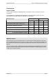
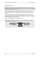
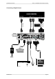
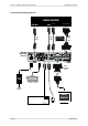
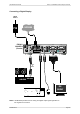

Table Of Contents
- What is VN-MATRIX?
- Functional Overview
- Example System Application
- Front Panel Features
- Rear Panel Features
- Accessories
- Choosing a Suitable Location
- Mains Power Connection (via PSU)
- Mains Power Cord (for PSU)
- Setup and Connection Procedure
- The VN-MATRIX Web Interface
- Configuring a VN-MATRIX as an Encoder (source)
- Configuring a VN-MATRIX as a Decoder (display)
- Troubleshooting
- Encoder Set Up
- Decoder Set Up
- System Set Up
- Overview
- Setting-up a Serial Data Stream
- Setting-up a Serial Passthrough Group
- Setting-up a Remote Control Group
- Serial / Telnet Commands
- Overview
- VN-MATRIX Hardware
- Serial Interface – Quick Reference
- Telnet Interface – Quick Reference
- Web Interface – Quick Reference
- Network Characteristics

VN-MATRIX User Guide Section 2: Installation & Basic Setup Procedures
I458GB issue 6 Page 35
Connections
Supplied Cables
A set of cables is supplied with VN-MATRIX to accommodate a variety of standard connection
requirements.
The VN-MATRIX is compatible with both digital (DVI) and analog graphics signals. The unit is
provided with the necessary additional cables that you may require.
Source (encoder) Display (decoder) Cable Description
Digital Analog Digital Analog
Mouse/Keyboard Cable (PS/2 to PS/2) (2 off)
Digital Monitor Cable (DVI-D to DVI-D)
Analog Monitor Cable (15-pin Hi-D D-type to DVI-A)
DVI-A to 15-pin Hi-Density D-type Adapter
For Connection Diagram see page…
37 38 39 40
IMPORTANT NOTES
Disconnecting and reconnecting PS/2 cables to a computer that is already switched on may cause
loss of mouse/keyboard control or cause the computer to ‘freeze’. It is recommended, therefore, that
the connections are made while the computer is powered-down. See also ‘Power-up Procedure’ on
page 28.
If you use a monitor cable or adapter other than that provided with the VN-MATRIX (as an encoder)
you must ensure that all pins are properly interconnected, otherwise the computer graphics card or
monitor may not operate correctly.