
User Guide User guide


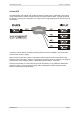
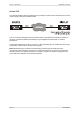


Table Of Contents
- What is VN-MATRIX?
- Functional Overview
- Example System Application
- Front Panel Features
- Rear Panel Features
- Accessories
- Choosing a Suitable Location
- Mains Power Connection (via PSU)
- Mains Power Cord (for PSU)
- Setup and Connection Procedure
- The VN-MATRIX Web Interface
- Configuring a VN-MATRIX as an Encoder (source)
- Configuring a VN-MATRIX as a Decoder (display)
- Troubleshooting
- Encoder Set Up
- Decoder Set Up
- System Set Up
- Overview
- Setting-up a Serial Data Stream
- Setting-up a Serial Passthrough Group
- Setting-up a Remote Control Group
- Serial / Telnet Commands
- Overview
- VN-MATRIX Hardware
- Serial Interface – Quick Reference
- Telnet Interface – Quick Reference
- Web Interface – Quick Reference
- Network Characteristics

Section 1: Introduction VN-MATRIX User Guide
Page 14 I458GB issue 6
Example System Application
The diagram below shows an example system application utilizing eight VN-MATRIX units. Four are
configured as encoders (sources) and four as decoders (displays). Each device is connected to a
network.
Configuration of each device, including which source is displayed on which display, can be achieved
by any PC/laptop on the same network, using the VN-MATRIX Integrated Web Management System.
SOURCE
2
SOURCE
1
These VN-MATRIX units are
configured as
decoders
One VN-MATRIX is designated as
a ‘controller’; this unit serves up
the Web Management System to
a browser running on any
networked computer
The Web Management System is
used to view or change settings
of all VN-MATRIX units on the
same network.
NETWORK
VN-MATRIX VN-MATRIX VN-MATRIX VN-MATRIX
SOURCE
1
SOURCE
2
SOURCE
3
SOURCE
4
VN-MATRIX VN-MATRIX VN-MATRIX VN-MATRIX
SOURCE
3
SOURCE
4
These VN-MATRIX units are
configured as
encoders
SOURCES
DISPLAYS
CONFIG
PC
In this example each of the four sources is shown separately on the four displays. Potentially
however, any display can display any source.