
User Guide User guide


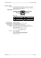
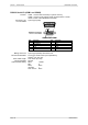
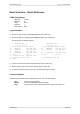
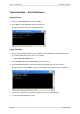


Table Of Contents
- What is VN-MATRIX?
- Functional Overview
- Example System Application
- Front Panel Features
- Rear Panel Features
- Accessories
- Choosing a Suitable Location
- Mains Power Connection (via PSU)
- Mains Power Cord (for PSU)
- Setup and Connection Procedure
- The VN-MATRIX Web Interface
- Configuring a VN-MATRIX as an Encoder (source)
- Configuring a VN-MATRIX as a Decoder (display)
- Troubleshooting
- Encoder Set Up
- Decoder Set Up
- System Set Up
- Overview
- Setting-up a Serial Data Stream
- Setting-up a Serial Passthrough Group
- Setting-up a Remote Control Group
- Serial / Telnet Commands
- Overview
- VN-MATRIX Hardware
- Serial Interface – Quick Reference
- Telnet Interface – Quick Reference
- Web Interface – Quick Reference
- Network Characteristics

Section 7: Technical Data VN-MATRIX User Guide
Page 104 I458GB issue 6
RS-232 Serial I/O (COM1 and COM2)
Function: COM1 – used for low level setup or system recovery.
COM2 – used for cross-network serial communications or serial
remote control of the VN-MATRIX controller.
Connector Type: 9-pin D-type (male)
Pin-out Details:
Pin Function Pin Function
1 DCD 6 DSR
2 RX (data in) 7 RTS
3 TX (data out) 8 CTS
4 DTR 9 RING
5 Ground
Mating Connector: 9-pin D-type (female) with metal cover
Recommended Cable: 6-core plus overall screen (low capacitance),
0.22mm
2
min. per core.
Max. Cable Length: 2.95 metres (9.5 feet).
Comms Standard: RS-232.
COM1 Default Setting: Baud: 115200
Bits: 8
Parity: None
Stop Bits: 1
Flow Control: None