
User Guide User guide


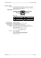
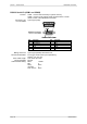
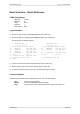
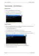


Table Of Contents
- What is VN-MATRIX?
- Functional Overview
- Example System Application
- Front Panel Features
- Rear Panel Features
- Accessories
- Choosing a Suitable Location
- Mains Power Connection (via PSU)
- Mains Power Cord (for PSU)
- Setup and Connection Procedure
- The VN-MATRIX Web Interface
- Configuring a VN-MATRIX as an Encoder (source)
- Configuring a VN-MATRIX as a Decoder (display)
- Troubleshooting
- Encoder Set Up
- Decoder Set Up
- System Set Up
- Overview
- Setting-up a Serial Data Stream
- Setting-up a Serial Passthrough Group
- Setting-up a Remote Control Group
- Serial / Telnet Commands
- Overview
- VN-MATRIX Hardware
- Serial Interface – Quick Reference
- Telnet Interface – Quick Reference
- Web Interface – Quick Reference
- Network Characteristics
VN-MATRIX User Guide Section 7: Technical Data
I458GB issue 6 Page 103
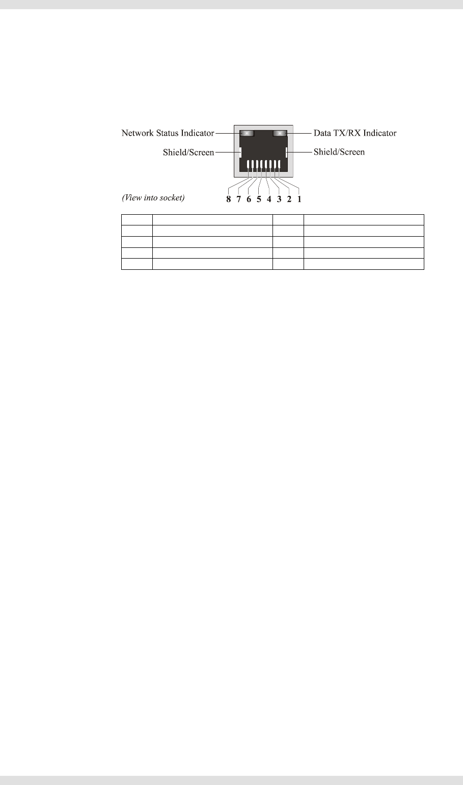
Network (I and II)
Function: Two separate network ports (labeled as I and II). Port I is used for
primary network connectivity (for data transport and configuration).
Port II is reserved for future expansion.
Connector Type: Shielded RJ-45 Socket.
Pin-out Details:
Pin Function Pin Function
1 TX_D1+ (TX+) 5 BI_D3–
2 TX_D1– (TX–) 6 RX_D2– (RX–)
3 RX_D2+ (RX+) 7 BI_D4+
4 BI_D3+ 8 BI_D4–
Mating Connector: Shielded RJ-45 Plug.
Recommended Cable: CAT 5E or CAT 6 Shielded twisted pair (STP).
Max. Cable Length: 100 metres (330 feet).
Comms Standard: 10/100/1000BASE-T (Gigabit Ethernet)
Ethernet (MAC)
Address:
Each address is unique and in the format 00:E0:AA:10:xx:yy
where yy is in the range 00 – FF and the same on both ports and
xx:is a hex value in the range 00 – 0A for port I
and 10 – 1B for port II.
For example: Port I: 00:E0:AA:10:00:18
Port II: 00:E0:AA:10:10:18
IP Address: Factory-set default is:
Port I: 192.168.0.1.
Port II: 192.168.1.12 (reserved for future use).
Both are user-definable via the serial interface.
Optional DHCP mode.