
User Guide User guide


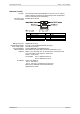
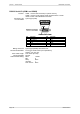
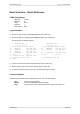
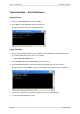


Table Of Contents
- What is VN-MATRIX?
- Functional Overview
- Example System Application
- Front Panel Features
- Rear Panel Features
- Accessories
- Choosing a Suitable Location
- Mains Power Connection (via PSU)
- Mains Power Cord (for PSU)
- Setup and Connection Procedure
- The VN-MATRIX Web Interface
- Configuring a VN-MATRIX as an Encoder (source)
- Configuring a VN-MATRIX as a Decoder (display)
- Troubleshooting
- Encoder Set Up
- Decoder Set Up
- System Set Up
- Overview
- Setting-up a Serial Data Stream
- Setting-up a Serial Passthrough Group
- Setting-up a Remote Control Group
- Serial / Telnet Commands
- Overview
- VN-MATRIX Hardware
- Serial Interface – Quick Reference
- Telnet Interface – Quick Reference
- Web Interface – Quick Reference
- Network Characteristics

VN-MATRIX User Guide Section 7: Technical Data
I458GB issue 6 Page 101
DVI Input (IN)
Function: Digital or analog video input for encoding.
Connector Type: DVI-I (female).
Pin-out Details:
Digital Connections
Pin Function Pin Function Pin Function
1 TMDS 2- 9 TMDS 1- 17 TMDS 0-
2 TMDS 2+ 10 TMDS 1+ 18 TMDS 0+
3 Ground (2/4) 11 Ground (1/3) 19 Ground (0/5)
4
nc
12
nc
20
nc
5
nc
13
nc
21
nc
6 DDC Clock 14 +5V supply* 22 Ground (Clk)
7 DDC Data 15 Ground (for 5v) 23 TMDS Clock+
8
Analog V-Sync
16 Hot Plug Detect 24 TMDS Clock-
* 5V supply is provided by VN-MATRIX and limited by 200mA polyswitch.
All ground pins are linked internally.
Analog Connections
Pin Function
C1 Red Signal
C2 Green Signal
C3 Blue Signal
C4 Horizontal Sync
C5 Ground
Mating Connector: DVI-D or DVI-I (male).
Recommended Cable: Supplied DVI cables.
Maximum Cable Length: 2.95 metres (9.5 feet).
Signal Type: DVI (PanelLink® TMDS).
Pixel Clock (DVI sources): Up to 162MHz.
Analog Sources: VGA 640x480 @ 60,72,75,85Hz
SVGA 800x600 @ 56,60,72,75,85Hz
XGA 1024x768 @ 60,72,75,85Hz
1152x864 @ 75Hz
SXGA 1280x1024 @ 60,75,85Hz
UXGA 1600x1200 @ 60Hz
Color Depth: 24-bit maximum.
Scan Mode: Progressive.
DVI Standard: DVI 1.0
Display Data Channel
Standard:
DDC2B.
DDC Levels: V
IH
= 2.4V
V
OH
= 0.9V
I
LOADMAX
= 2mA
NOTE:
Analog Vertical Sync
is on pin 8.