
User Guide Owner's manual
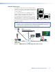

5. Connect the ground connector of the first slave device to the ground connector of the
second slave device.
6. Connect the genlock out from the first slave device to the genlock in of the second
slave device.
7. Repeat steps 5 and 6 to link as many slave devices as required.
Video Connections
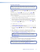
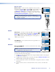
HDMI input (VNE 250) — connect an HDMI digital video source
to this port (see figure 6,
G
on page 13). For a list of supported
modes, see the Specifications on the VNM 250 web page at
www.extron.com.
HDMI loop-through (VNE 250) — provides fully buffered
output of all data from the HDMI input source. Connect a local
HDMI monitor to this port (see figure 6,
H
on page 13).
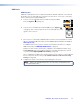
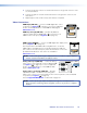
HDMI output (VND 250) — connect an HDMI digital video display to this
port (see figure7,
I
on page 13).
Use the provided LockIt HDMI Cable Lacing Brackets to secure the
HDMI cables to the VND 250 (one screw above the port) or VNE 250
(two screws to the sides of the port). Follow the instructions on the card
provided with the brackets. This card is also available at
www.extron.com.
NOTE: A full‑screen green image is displayed when a non‑HDCP compliant display is
used in conjunction with HDCP‑encrypted content.
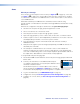
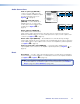
Analog video input (VNE 250) — connect an analog
video source to the 15‑pin HD connector labelled "RGB"
(see figure 6,
K
on page 13). For a list of supported
modes, see the Specifications on the VNM 250 web
page at www.extron.com.
Analog video loop-through (VNE 250) — provides
fully buffered output of all data from the analog video
input source. Connect a local analog video monitor to the 15‑pin HD connector labelled
"Loop Thru" (see figure6,
L
on page13).
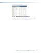
A list of Supported EDID Modes can be found on page 122.
NOTE: Both loop‑through outputs will display the image from the input that has
been selected for streaming. HDCP‑encrypted content is only shown on compliant
displays.
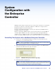
LOOP THRU
LOOP
THRU
RGB
AUDIO
L R
INPUT 2
L
OO
P
T
HR
U
A
U
DI
O
HDMI
LOOP THRU
INPUT 1
HDMI
OUTPUT
VNM 250 • Rear Panel and Connections 20