
User Guide Owner's manual

RS-232 control
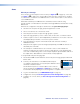
RS-232 control — allows low level configuration of the encoder or
decoder. Use the three poles to the right of the shared captive screw
connector (see figure 6,
R
, or figure 7,
R
on page 13). See
the Attention and Note boxes on page 14 for information about
preparing and connecting wires to a captive screw connector. See
Low Level Device Configuration on page 24.
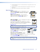
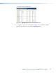
NOTE: The RS‑232 pins are not in the standard Extron
orientation. Ensure that the connector is correctly wired (see
the figure to the right).
Alarms
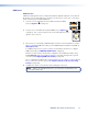
Alarm relays — provide a normally open (NO) contact. Use the first
two poles of a shared captive screw connector (see figure 6,
S
or
figure7,
S
on page 13). See the Attention and Note boxes on
page 14 for information about preparing and connecting wires to a
captive screw connector.
TTL
TTL (VNE 250) —the TTL (Transistor‑transistor logic) feature is not
currently supported.
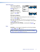
Genlock
Genlock I/O (VND 250) —is used to synchronize the video output
on multiple decoders.
NOTE: The VND 250 uses TTL level signalling, which is not
compatible with normal genlock sources.
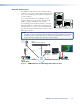
One decoder is selected as the reference (master) unit, and provides the signal that is used
to synchronize all the other units (slaves).
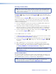
1. Configure one decoder as the Master unit, using the web‑based GUI control program
(see Genlock on page59).
2. Configure all the other decoders as slaves by selecting the Genlock check box of the
web‑based GUI control program (see page 59).
3. Connect the Ground connector of the master unit to the ground connector of the first
slave device.
4. Connect the Out connector of the master unit to the In connector of the first slave
device.
ALARM GENLOCK
NO GINGOUT
I/O
G
ENL
OC
K
IN
G
O
U
T
Tx Rx
PASS THRU CONTROL
GTxRx
COMS
Tx
Rx
P
ASS THR
U
ALARM TTL
NO GINGOUT
I/O
A
LAR
M
NO
G
ALARM GENLOCK
NO GINGOUT
I/O
A
LARM
N
O
G
RS-232 Connector
Wiring
Receive
Transmit
Ground
Tx Rx
PASS THRU CONTROL
GTxRx
COMS
Tx
Rx
P
A
SS
THR
U
P
VNM 250 • Rear Panel and Connections 19