
User Guide Owner's manual
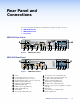

Rear Panel and
Connections
This section describes the VNE 250 and VND 250 rear panels and the connectors:
z VNE 250 Rear Panel
z VND 250 Rear Panel
z Connections
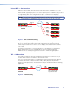
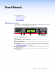
VNE 250 Rear Panel
LAN 1
LAN 2
PC
RESET
HDMI
LOOP THRU LOOP THRU
LOOP
THRU
RGB
/ACT
LINK
2.0 A MAX
POWER
12V
AUDIO
L
Tx Rx
PASS THRU ALARM TTLCONTROL
GTxRxNOC IN GOUT
R
RETURN AUDIO
L R
STREAMINGCONTROL
USB
INPUT 1
INPUT 2
COMS
I/O
OUTPUT
A
B
C
P
DTSRNEMGH JK
L
Figure 6. VNE 250 Rear Panel
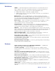
VND 250 Rear Panel
LAN 1
LAN 2
RESET
HDMI
/ACT
LINK
2.0 A MAX
POWER
12V
AUDIO
L
Tx Rx
PASS THRU ALARM GENLOCKCONTROL
GTxRxNOG IN GOUT
R
RETURN AUDIO
LR
STREAMINGCONTROL
COMS INPUT
I/O
OUTPUT
OUTPUT
1
2
USB
A
B
CD FUSROJI
Q
Figure 7. VND 250 Rear Panel
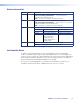
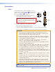
A
Power
B
Control Network RJ‑45 connector
C
Streaming Network RJ‑45 connector
D
Streaming Network SFP connector (optional)
E
USB port, type B (VNE 250)
F
USB ports, type A (VND 250)
G
HDMI input (VNE 250)
H
HDMI loop‑through (VNE 250)
I
HDMI output (VND 250)
J
Reset button
K
Analog video input (VNE 250)
L
Analog video loop‑through (VNE 250)
M
Program audio loop‑through (VNE 250)
N
Program audio input (VNE 250)
O
Return audio input (VND 250)
P
Return audio output (VNE 250)
Q
Program audio output (VND250)
R
RS‑232 coms (low level configuration and pass
through)
S
Alarm relay
T
TTL (VNE 250: not implemented)
U
Genlock (VND 250)
VNM 250 • Rear Panel and Connections 13