
Setup Guide Manual

Connections
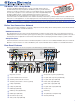
1. Connect a power supply to the VNM 250 devices (rear panel diagrams,
a
).
2. Connect the Streaming Network ports (LAN 2) of all the devices to the network (
c
or
d
).
NOTE: For normal operation, the Control Network port (LAN 1) (
b
) is not required.
3. Make the video connections:
a. Connect an HDMI source to the HDMI input port (
g
) or an analog source to the analog input port (
k
) of the VNE 250.
Both input types can be connected but only one output as a stream at any one time.
b. Connect displays to the HDMI loop-through port (
h
) or the analog loop-through port (
l
) of the VNE 250, if required.
c. Connect a HDMI display to the HDMI output port (
i
) of the VND 250.
4. Make the program audio connections (optional):
a. Connect the program audio to the ve-pole, program audio captive screw input (
n
) of the VNE 250.
b. Connect an amplier and speakers to the program audio loop-through TRS connector (
m
) of the VNE 250, if required.
c. Connect amplier and speakers to the program audio ve-pole captive screw output (
q
) of the VND 250.
5. Make the return audio connections (optional):
a. Connect the return audio to the to the ve-pole, return audio captive screw input (
o
) of the VND 250.
b. Connect amplier and speakers to the return audio ve-pole captive screw output (
p
) of the VNE 250.
6. Make the pass-through data transfer connections (optional):
a. For RS-232 pass-through, one VNM 250 device will be the server (connected to a control PC or other control device) and
one or more VNM 250 devices will be connected to the equipment that is to be controlled (clients). Either the encoder or
the decoder can act as the server. Connect the three left pins of the RS-232 Coms port on the server (
r
) to the serial
port of a PC (pin 1 = Tx, pin2= Rx, and pin 3 = Ground).
b. Connect the three left pins of the RS-232 Coms port on the clients (
r
) to the devices that are to be controlled
(pin1=Tx, pin 2 = Rx, and pin 3 = Ground).
7. Connections to the remaining ports on the VNM 250 units are optional. Follow the instructions provided in the VN-Matrix250
Series User Guide on www.extron.com.
After making the connections described above, you must congure the system. Initial, low-level conguration is described in the
next section. More advanced conguration requires system controller GUI control. See the VNM 250 Series User Guide.
Initial Configuration
1. Before starting, talk to your network administrator to obtain IP addresses for all units in the system.
2. Make connections for the low-level conguration of the VNM 250 unit. Connect the serial port of a PC to the three right pins
of the RS-232 Coms port (pin 3 = Ground; pin 4 = Tx; pin 5 = Rx).
NOTE: This connection is required for low level configuration only but not for normal operation. It does not need to
remain in place once the device is configured.
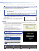
3. Open Extron DataViewer on the PC. In the opening dialog box, ensure the communications settings are:
●
Baud rate = 115200
●
Data bits = 8
●
Parity = none
●
Stop bits = 1
●
Flow control = none.
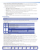
4. When prompted, enter the login and password. By default both the login and password are config. The low level
conguration menu opens:
Control Network port
====================
Streaming Network port
======================
0. Speed/Duplex: auto_10_100_1000
1. IP Prov mode: static [dhcp]
2. address: 192.168.253.254
3. netmask: 255.255.255.0
6. mtu: 1500
7. VLAN ID: 0
8. controller ip: 192.168.254.254
9. Exit
10. Speed/Duplex: auto_10_100_100
0
11. IP Prov mode: static [dhcp]
12. address: 192.168.254.254
13. netmask: 255.255.255.0
14. gateway: 192.168.254.1
16. mtu: 1500
17. VLAN ID: 0
18. Controller port: 5432
19. webserver port: 80
Please select an option:
2