
Setup Guide Manual

1
VN-Matrix
®
250 • Setup Guide
The Extron VN-Matrix (VNM) 250 Series consists of the VNE 250 encoder and
the VND250 decoder. They integrate into VN-Matrix systems to provide real-time
transmission of high resolution AV content across standard IP networks. The VNE250
encodes video or graphics sources at resolutions up to HD or 2K (2048x1080) using
the Extron PURE3™ Codec, a unique wavelet-based compression technology.
The VND250 decodes the content back to the original source resolution or a user
selected resolution. The VNM 250 Series offers real-time streaming and low latency, making it ideal for remote collaborative and
interactive or control applications. It can be deployed in live event streaming and high level conferencing for specialized projects.
NOTE: For full installation, configuration, and operation details, refer to the VN-Matrix 250 User Guide, at www.extron.com.
Before You Connect to a Network
Before connecting each VN-Matrix to a network, congure the network settings. On an existing network, check with the network
administrator for a range of suitable IP addresses.
VN-Matrix Controller
One VN-Matrix device in the system must be designated the controller. For large systems (ten or more devices) this must be a
VNM Enterprise Controller. For smaller systems (up to ten devices), the controller may be a VNM 250 device (either an encoder or
decoder). All system conguration is achieved via a web interface that is served up by the device acting as system controller.
Setup Procedure
Follow the instructions in the Connections and Initial Conguration sections for each individual VN-Matrix device, then follow the
Operation section instructions to create a VN-Matrix system. See the VN-Matrix 250 User Guide for more detailed information.
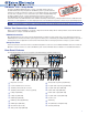
Rear Panel Features
The following illustration shows the rear panels of the VND 250 (top) and VNE 250 (bottom):
LAN 1
LAN 2
RESET
HDMI
ACT/
LINK
2.0 A MAX
POWER
12V
AUDIO
L
Tx Rx
PASS THRU ALARM GENLOCKCONTROL
GTxRxNOG IN GOUT
R
RETURN AUDIO
LR
STREAMINGCONTROL
COMS INPUT
I/O
OUTPUT
OUTPUT
1
2
USB
1
2
3 4 6 9
15
18
17
1910 21
LAN 1
LAN 2
PC
RESET
HDMI
LOOP THRU LOOP THRU
LOOP
THRU
RGB
ACT/
LINK
2.0 A MAX
POWER
12V
AUDIO
L
Tx Rx
PASS THRU ALARM TTLCONTROL
GTxRxNOG IN GOUT
R
RETURN AUDIO
L R
STREAMINGCONTROL
USB
INPUT 1
INPUT 2
COMS
I/O
OUTPUT
1
2
3 4 5 8
7
11
13
14
12 18
16
1910 20
a
DC power connector
l
Analog video loop-through (VNE 250)
b
Control network RJ-45 connector
m
Program audio loop-through (VNE 250)
c
Streaming network RJ-45 connector
n
Program audio input (VNE 250)
d
Streaming network SFP connector (optional)
o
Return audio input (VND 250)
e
USB port (VNE 250)
p
Return audio output (VNE 250)
f
USB ports (VND 250)
q
Program audio output (VND 250)
g
HDMI input (VNE 250)
r
RS-232 coms
h
HDMI loop-through (VNE 250)
s
Alarm relay
i
HDMI output (VND 250)
t
TTL (VNE 250; not implemented)
j
Reset button (recessed)
u
Genlock (VND 250)
k
Analog video input (VNE 250)