
Installation Owner manual

VGA + RCA to Captive Screw Modules User's Guide, cont’d
PRELIMINARY
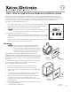
VGA connections
HD-15 pin TRS Captive Screw pin Color
1 Red* R Red coax
2 Green* G Green coax
3 Blue* B Blue coax
4 ID Bit 2 N/A Green (Not used)
5 Ground
(right block)
Violet
6 Red Gnd* Rg Red coax shield
7 Green Gnd* Gg Green coax shield
8 Blue Gnd* Bg Blue coax shield
9 DDC +5V* (see
note at right)
+5 Gray
10 Sync Gnd*
(main block)
Black (red/black pair)
11 ID Bit 0 N/A Blue (Not used)
12 ID Bit 1 or DDC D Yellow
13 H sync* H Red (red/black pair)
14 V sync* V White (white/black pair)
15 ID Bit 3 or Clock C Black (white /black pair)
* Tip Audio T (Left) Orange
* Ring Audio R (Right) Brown
* Sleeve Audio S (Ground) Shield
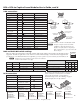
DDC and ID bit DIP switch settings
These two tables show the function of the DIP switches (table at left) and how the switches can affect the monitors
supported. The table at right shows some of the more common ID bit settings. Check the manual supplied with
your display to see if ID bit termination is required by your A/V system. If you are unsure, set all switches to off.
N
If DDC is to be used, switches 1 and 3 must be set to on and
switches 2 and 4 must be set to off.
Switch ID bit pin Off On
1 ID 0 HD-15 pin 11 open HD-15 pin 11 to ground
2 ID 1 HD-15 pin 12 pass-through HD-15 pin 12 to ground
3 ID 2 HD-15 pin 4 open HD-15 pin 4 to ground
4 ID 3 HD-15 pin 15 pass-through HD-15 pin 15 to ground
RCA connections
RCA Connector Signal Captive Screw pin
Video Tip Composite Video V
Video Sleeve Video Ground
GND ( )
Left Audio Tip Left Audio
(Unbalanced -10 dBV)
L
Left Audio Sleeve Left Audio Ground
GND ( )
Right Audio Tip Right Audio Ground
GND (
)
Right Audio Sleeve Right Audio
(Unbalanced -10 dBV)
R
©
2009 Extron Electronics. All rights reserved.
Extron
USA - West
Headquarters
+800.633.9876
Inside USA / Canada Only
+1.714.491.1500
+1.714.491.1517 FAX
Extron
USA - East
+800.633.9876
Inside USA / Canada Only
+1.919.863.1794
+1.919.863.1797 FAX
Extron
Europe
+800.3987.6673
Inside Europe Only
+31.33.453.4040
+31.33.453.4050 FAX
Extron
Asia
+800.7339.8766
Inside Asia Only
+65.6383.4400
+65.6383.4664 FAX
Extron
Japan
+81.3.3511.7655
+81.3.3511.7656 FAX
Extron
China
+400.883.1568
Inside China Only
+86.21.3760.1568
+86.21.3760.1566 FAX
Extron
Dubai
+971.4.2991800
+971.4.2991880 FAX
Tip (+)
Sleeve ( )
RCA Connector
L
R
V
Labels for captive
screws match RCA
connectors, as shown
in the table at left.
5 1
15 11
610
HD15 Female
Pin Locations
Sleeve ( )
Ring (
-
)
Tip (+)
3.5 mm Stereo
Plug Connector
(balanced)
Sleeve ( )
Ring (R)
Tip (L)
3.5 mm Stereo
Plug Connector
(unbalanced)
Captive Screw
Connectors
D
C
*
*
*
*
*
*
*
*
*
*
Connectors labeled in
gray are optional.
*
*
*
*
*
R GgRg
G BgB
H V
+5
+5
T SR
Labels for captive
screws match HD-15
pins, as shown in
the table at left.
The wiring for the three RCA plugs to the captive
screw connectors is shown below. Cut all the
wires to the same length. Connect them as
described in steps 5-7 of "VGA Wiring" on page 1.
The RCA inputs have no dip switches.
Display used DIP switch
1 2 3 4
No ID bit required Off Off Off Off
Monochrome monitor (not XGA) On Off Off Off
Color monitor (not XGA) Off On Off Off
Color monitor (supports XGA) Off On On Off
* Cut these wires 1" shorter. See the table at left.
N
VGA pin 9 may be used to detect DDC
availability. Check the manual for your
display to see if this feature is required for
DDC communication. If you are unsure, do
not use the pin.
1 2 3
4
ON
DIP Switches
2
w
ww.extron.com