
Installation Owner manual

VGA + RCA to Captive Screw Modules Installation Guide
PRELIMINARY
WPC 170 MK
VIDEO AUDIO
COMPUTER AUDIO
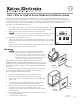
The Extron VGA + RCA to Captive Screw modules provide a series of wall mounted plates that accept video and
audio signals through one female HD 15 connector and one 3.5 mm Tip-Ring-Sleeve (TRS) connector. Depending on
the style, there may also be three RCA receptacles. The signals are output from the back of the unit via captive screw
connectors. The captive screw connectors will take wires 18 AWG (1.02 mm) to 26 AWG (0.404 mm) in size.
The units come in three different form factors:
• EU, which mounts onto European junction boxes (WPC 150 EU and WPC 170 EU)
• MK, which mounts onto UK junction boxes (WPC 150 MK and WPC 170 MK)
• MAAP, which mounts onto Extron's three-space MAAP products
N
In North America, the product must be installed only in UL-listed products or
in a listed junction box, in accordance with the National Electrical Code.
Each form factor is available in two styles:
• The VGA + RCA style has a female HD-15 receptacle (RGB video), a 3.5 mm TRS
receptacle (balanced or unbalanced audio), and three RCA plugs (composite video
and audio).
•
The VGA/Audio style has a female HD 15 receptacle (RGB video) and a 3.5 mm
TRS receptacle (audio). There are no RCA inputs.
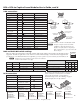
VGA Wiring
N
Extron recommends Extron MHR VGA bulk cable (part
number 22-024-01) or assembled cables (part numbers
26-112-15, 26-112-36, 26-238-01, and 26-238-25). The wire
colors for these products are shown in the VGA Connections
table at the top of page 2. If other cable products are used, the
colors may not correspond to those shown in the table.
The minimum output wiring requirements for these modules are
RGBHV and audio. The DDC and ID bit DIP switches, the +5 V pin, and
the DDC pins are optional but they can affect the monitors supported by
the system (see the table at right of "DDC and ID bit DIP switch settings"
on page 2).
To connect wires from the VGA input to these modules, the wires must
be cut to different lengths (see the table in the "VGA Connections"
section on page 2). Follow these instructions:
1
. Run the unterminated end of the cable to the junction box.
2. Strip away 3 inches from the end of the cable's outer jacket.
3. Unravel each of the coaxial shields and twist each, individually, to
make a wire.
4
. Cut 1 inch from the end of the individual wires marked with an
asterisk in the VGA Connections table on the next page.
5
. Strip 3/16 inch (5 mm) of the inner jacket from the end of each
wire and secure the wire to the appropriate captive screw
connector (see the VGA Connections and RCA Connections tables
on the next page).
6
. Secure the faceplate to the junction box using the screws provided
(see the figures at right).
7
. Connect the video/audio device.
68-1636-01
Rev. B 09 09
WPC 150 MK
COMPUTER
AUDIO
30 mm M3.5
Screws (2)
UK Junction Box
Extron
WPC 150 MK
WPC 170 EU
VIDEO AUDIO
COMPUTER
AUDIO
EU Junction Box
20 mm M3
Screws (2)
Extron
WPC 170 EU
1