
Setup Guide Owner's manual

Refer also to the VersaTools
®
MTP Series User’s Manual at www.extron.com.
C
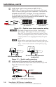
The length of exposed wires is critical. Ideal length is
3/16” (5 mm). If the stripped section of wire is longer than
3/16” the exposed wires may touch, causing a short circuit.
If the stripped section of wire is shorter, wires can easily be
pulled out even if tightly fastened by the captive screws.
N
Do not tin the stripped leads! Tinned wires are not as
secure in the captive screw and direct insertion connectors
and could be pulled out.
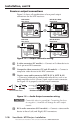
Verify the polarity before connection! Plug in the power supply
in with no load and check the output with a voltmeter.
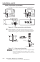
W
The two power cord wires must be kept separate while the
power supply is plugged in. Remove power before wiring.
Use the supplied tie‑wrap to strap the power cord to the
extended tail of the connector.
N
The transmitter/receiver pair may have shipped with a blue
captive screw connector. This connector does not include
the extended tail or tie-wrap but can be plugged into either
a blue or an orange power receptacle.
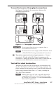
Transmitter/receiver combinations containing new generation,
non‑jumpered (mono audio) units cannot be powered from a
single supply. The following table shows the combination of
old and new generation MTP units (jumper congured to the
stereo audio position) capable of remote powering (See "Signal
Jumpers for Generational Compatibity" on page 1‑3).
Single Power Supply (remote powering)
Transmitter Receiver
Old Generation Old Generation
Old Generation New Generation, Jumpered*
New Generation, Jumpered* Old Generation
New Generation, Jumpered* New Generation, Jumpered*
*Congured for stereo audio
N
When configured for stereo audio, a single power supply
connected to either the transmitter or receiver can power
both units if there is less than 500 feet (150 meters) of
STP/UTP/FTP cable between the two. If the transmitter
and receiver are separated by greater than 500 feet, connect
a power supply to both units regardless of the model and
jumper configuration.
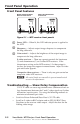
g
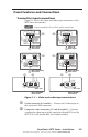
Power LED — Indicates power is applied to the MTP.
VersaTools
®
MTP Series • Installation
1-9