User’s Guide VersaTools® MTP Series Video and Audio Mini Twisted Pair Transmitters and Receivers www.extron.com Extron Electronics, USA 1230 South Lewis Street Anaheim, CA 92805 800.633.9876 714.491.1500 FAX 714.491.1517 Extron Electronics, Europe Beeldschermweg 6C 3821 AH Amersfoort, The Netherlands +800.3987.6673 +31.33.453.4040 FAX +31.33.453.4050 Extron Electronics, Asia 135 Joo Seng Rd. #04-01 PM Industrial Bldg., Singapore 368363 +800.7339.8766 +65.6383.4400 FAX +65.6383.
Precautions Safety Instructions • English This symbol is intended to alert the user of important operating and maintenance (servicing) instructions in the literature provided with the equipment. This symbol is intended to alert the user of the presence of uninsulated dangerous voltage within the product's enclosure that may present a risk of electric shock. Caution Read Instructions • Read and understand all safety and operating instructions before using the equipment.
FCC Class A Notice This equipment has been tested and found to comply with the limits for a Class A digital device, pursuant to part 15 of the FCC Rules. Operation is subject to the following two conditions: (1) this device may not cause harmful interference, and (2) this device must accept any interference received, including interference that may cause undesired operation.
Table of Contents Chapter 1 • Introduction .......................................................... 1-1 About the MTP Transmitters and Receivers ............ 1-2 TP Cable Advantages ........................................................... 1-2 Transmission Distance ......................................................... 1-2 Chapter 2 • Installation ............................................................. 2-1 Signal Jumpers for Generational Compatibility ...
Table of Contents, cont’d VersaTools® MTP Series 1 Chapter One Introduction About the MTP Transmitters and Receivers TP Cable Advantages Transmission Distance All trademarks mentioned in this manual are the properties of their respective owners. 68-732-01 Rev.
Introduction About the MTP Transmitters and Receivers MTP T SV A MTP T SV A RCA MTP T SVA AAP MTP T CV Audio versions of the transmitter are available that input either balanced or unbalanced audio on captive screw connectors or unbalanced audio on RCA connectors. The transmitters sum the left and right audio channels to convert the audio to mono (L+R) format.
Introduction, cont’d • The video portion of any S-video transmitter’s output is compatible with any S-video receiver in the MTP family described in this manual if the transmitter and receiver jumper configuration are compatible. See “Signal Jumpers for Generational Compatibility”, in chapter 2, “Installation”.
Installation Installation and service must be performed by authorized personnel only. Over time, the MTPs have been redesigned, affecting the signal content of the TP cable wire pairs, changing the audio from stereo to mono, and eliminating the remote power capability. The new-generation units are not compatible with the old generation unless an internal jumper in the new unit is shifted.
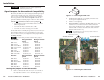
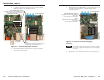
Installation, cont’d 5. Locate the jumper blocks (figure 2-3) on the video board. Shift the jumper to the alternate location. Mono (default jumper position) Compatible with new model transmitter/receivers. Cannot remotely power transmitter/receiver Transmitter Front Panel 7. If the receiver is an audio unit, locate the jumper block on the audio board (figure 2-4). Shift the jumper to the alternate location.
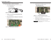
Installation, cont’d Setting the jumpers on AAP transmitters 1. 4. Remove and retain the two screws that secure the back cover to the MTP (figure 2-5). Locate the jumper block (figure 2-7) on the video board. Shift the jumper to the alternate location. Mono (default jumper position) Compatible with new model receivers. Cannot remotely power receiver 2. Carefully pull RJ-45 connector through this hole. 1. Remove these screws. OUTPUT − + POWER 12V 0.5A MAX Figure 2-5 — Removing the MTP cover 2. 3.
Installation, cont’d Mounting Options Tabletop use (all except AAP models) The non-AAP MTPs come with self-adhesive rubber feet attached to the four corners of the bottom. Set the MTP on a horizontal surface.
Installation, cont’d Rack mounting instructions On the standard rack shelf, the MTP mounts in one of eight locations to the rear of the rack or in one of eight locations to the front of the rack. 1. Remove the feet from the bottom of the MTP, if installed. 2. Mount the MTP using two 4-40 x 3/16" screws in opposite (diagonal) corners to secure the MTP to the shelf. 3. Install blank panel(s) or other unit(s) to the rack shelf. 4. d.
Installation, cont’d 2. Cable the rear of the transmitter before fastening the AAP module to the AAP frame. 1 S-video connector (SV models) — Connect an S-video input to this 4-pin mini DIN connector. 3. Insert each of the AAP module’s screws through the holes in the AAP frame. Secure the transmitter to the frame with the provided captive washers and #4-40 nuts.
Installation, cont’d When making connections for the MTP from existing audio cables, see figure 2-14 to identify the tip, ring, and sleeve wires in various connectors. A mono audio connector consists of the tip and sleeve. A stereo audio connector consists of the tip, ring and sleeve. The ring, tip, and sleeve wires are also shown on the captive screw audio connector diagrams, figure 2-13 and figure 2-21.
Installation, cont’d TP cable termination The green, brown, and blue pairs of this cable have virtually identical lengths and should be used to transmit the video signals. Figure 2-17 details the recommended termination of TP cables with RJ-45 connectors in accordance with the TIA/EIA T 568A or TIA/EIA T 568B wiring standards. You can use either standard, but ensure that you use the same standard on both cable ends.
Installation, cont’d If the transmitter and receiver are either older generation units or jumper configured to the stereo audio position (compatible with the older units), only a single device needs to be powered in a two-unit system. See “Signal Jumpers for Generational Compatibility” on page 2-2. The device connected to the power supply, in turn, provides power to its counterpart. Receiver output connections See figure 2-20 to identify the receivers’ rear panel output connections.
Installation, cont’d 10 Captive screw audio connector (MTP R SV A, MTP R AV) — Connect a balanced or unbalanced audio device, such as an audio amplifier to this 3.5 mm, 5-pole captive screw connector. See figure 2-21 to properly wire the output connector. NO GROUND HERE. Do not tin the wires! Unbalanced Stereo Output Tip Ring Sleeve(s) Tip Ring R Sleeve(s) Tip L Tip NO GROUND HERE.
Operation Front Panel Features 1 SHARP 2 C GAIN 3 VersaTools® MTP Series MTP R S-video Receiver Front Panel Y GAIN SHARP 1 GAIN MTP R Composite Video Receiver Front Panel 3 3 2 Figure 3-1 — MTP receiver front panels 1 Power LED — When lit, this LED indicates power is applied to the MTP. 2 Sharpness — Adjusts the output image sharpness for long cable runs. 3 Gain control — Adjusts the brightness of the output image to compensate for long cable runs.
Specifications, Part Numbers, and Accessories Specifications Return loss .................................... <-35 dB @ 5 MHz DC offset ....................................... ±20 mV with input at 0 offset Video Gain ............................................... Unity Differential phase error .............. <1.0º at 3.58 MHz and 4.43 MHz Differential gain error ................. <1.0% at 3.58 MHz and 4.43 MHz Minimum/maximum levels ...... Impedance .................................... Return loss .....
Specifications, Part Numbers, Accessories, cont’d Audio output — audio models (A, AV, SVA models) only Number/signal type MTP T Series (all models) 1 set of proprietary analog signals MTP R AV, MTP R SV A 1 stereo or dual mono, balanced/ unbalanced MTP R AV/SV A RCA .... 1 stereo or dual mono, unbalanced Connectors MTP T Series .................... 1 female RJ-45 (shielded) MTP T AAP Series ........... 1 female RJ-45 on a 3" (7.6 cm) pigtail MTP R AV, MTP R SV A (1) 3.
Specifications, Part Numbers, Accessories, cont’d Cables/connectors Part Numbers MTP transmitters Description Part number to reorder MTP T SV MTP T SV A MTP T SV A RCA MTP T SV A AAP (black, white) MTP T CV MTP T AV MTP T AV RCA MTP T AV AAP (black, white) 60-540-42 60-540-52 60-541-62 70-362-22, 23 60-540-41 60-540-51 60-540-61 70-361-22, 23 MTP receivers Description Part number MTP R SV MTP R SV A MTP R SV A RCA MTP R CV MTP R AV MTP R AV RCA 60-541-42 60-541-52 60-541-62 60-541-41 60-541-51 60-54
Specifications, Part Numbers, Accessories, cont’d A-8 VersaTools® MTP Series • Reference Information