User’s Manual TSC 100 www.extron.com Extron Electronics, USA Extron Electronics, Europe Extron Electronics, Asia Extron Electronics, Japan 1230 South Lewis Street Anaheim, CA 92805 USA 714.491.1500 Fax 714.491.1517 Beeldschermweg 6C 3821 AH Amersfoort The Netherlands +31.33.453.4040 Fax +31.33.453.4050 135 Joo Seng Road, #04-01 PM Industrial Building Singapore 368363 +65.6383.4400 Fax +65.6383.4664 Daisan DMJ Building 6F 3-9-1 Kudan Minami Chiyoda-ku, Tokyo 102-0074 Japan +81.3.3511.7655 Fax +81.3.
Precautions Safety Instructions • English This symbol is intended to alert the user of important operating and maintenance (servicing) instructions in the literature provided with the equipment. This symbol is intended to alert the user of the presence of uninsulated dangerous voltage within the product's enclosure that may present a risk of electric shock. Caution Read Instructions • Read and understand all safety and operating instructions before using the equipment.
Quick Start Guide — TSC 100 To install and set up the TSC 100, follow these steps: Step 1 Turn all of the equipment off and disconnect it from the power source. Step 2 Rack mount the TSC 100, or place it on a desktop. See “Rack Mounting the TSC 100” in chapter 2, Installation and Operation. Step 3 Attach the input cable(s). See “Cabling the TSC 100” in chapter 2, Installation and Operation. Step 4 Attach output and loopout cables, then attach an RS-232/422 controller (if desired).
Quick Start Guide — TSC 100, cont’d Table of Contents Chapter 1 • Introduction .......................................................... 1-1 Step 6 Select an input and an output standard using the front panel buttons or the RS-232 controller. Step 7 The picture should now appear. If not, ensure that all devices are plugged in and receiving power. Check the cabling and make adjustments as needed. Select a different input to check for a display. About the TSC 100 .........................................
Table of Contents, cont’d TSC 100 1 Chapter One Introduction About the TSC 100 Features ii TSC 100 • Table of Contents
Introduction About the TSC 100 The Extron TSC 100 is a transcoder and standards converter that allows worldwide compatibility with video standards such as NTSC 3.58, NTSC 4.43, SECAM, and PAL. As a transcoder, it is able to take one video format, such as an analog composite signal, and transcode it into another video format, such as an S-video signal. It provides picture adjustment capability as well as RS-232/RS-422 control.
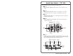
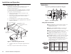
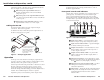
Installation and Operation Rack Mounting the TSC 100 Connections In addition to using the TSC 100 on a desktop, it can also be rack mounted. To rack mount the TSC 100, follow the installation instructions below. All connections, including power, input and output, and control, are on the rear panel of the TSC 100. See figure 2. 2 For optional rack mounting, mount the TSC 100 on a standard, 19" 1U Rack Shelf (Extron part #60-190-01) (figure 1) in one of four locations on the front of the rack. 1.
Installation and Operation, cont’d Software for RS-232 or RS-422 control is included with the TSC 100. See chapter 3, Serial Control for details. 6 Buffered loopout composite BNC connector — Connect one BNC female connector for buffered composite loopout. 7 Buffered loopout S-video 4-pin mini-DIN connector — Connect one 4-pin mini DIN connector for buffered S-video loopout. 8 Output 4-pin S-video mini DIN connector — One 4-pin mini DIN connector for S-video output.
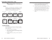
Installation and Operation, cont’d 8 Min / Max indicator LED — A red LED lights to indicate when the minimum or maximum adjustment levels are reached. Presets When PAL is converted to NTSC or when NTSC is converted to PAL, the aspect ratio of the display can be distorted. In order to correct this distortion, six presets (shown in figure 5) are available. Please refer to chapter three, RS-232 Control, for information on choosing and using these presets.
Installation and Operation, cont’d TSC 100 3 Chapter Three Serial Control Programmer’s Guide for Serial Communication Control Software for Windows® 2-8 TSC 100 • Installation and Operation
Serial Control, cont’d Programmer’s Guide for Serial Communication The TSC 100 can be controlled by a host computer or other control device via an RS-232/422 connection with the following protocol: • 9600 baud • 1 stop bit • no parity • no flow control The control device can use either Extron’s Simple Instruction Set™ (SIS™) or the Extron graphical control program for Windows®.
3-4 TSC 100 • Serial Control TSC 100 • Serial Control Specific value Example: Contrast Specific value Example: Increment tint value Decrement tint value View tint value Tint Specific value Example: Increment color value Decrement color value View color value = ^ 29 ^ X7 X2 T 29T +T -T T 29C +C -C C X7 C = View video type Color 1= X6 X1 ! Set video output standard Example: Video output standard Select input source X6 X1 Con X7 Con 29 X2 Tin X2 Tin 29 Tin X2 Tin X2 X7 Col X7 Col 29
3-6 ^ View contrast value TSC 100 • Serial Control View top value +) -) ) Increase top value Decrease top value View top value Specific value X3 -( ( Decrease top value Bottom blanking +( X3 1X 0X X +; -; ; X8 ) ( ; TSC 100 • Serial Control Blb Blb Blb Blb Blt Blt Blt Blt X4 X8 X8 X8 X8 X3 X3 X3 X3 View the number of lines blanked at bottom. Decrease the number of bottom lines blanked. Increase the number of bottom lines blanked.
3-8 TSC 100 • Serial Control n/N i/I q/Q J 1J 0J Example Aspect Ratio Example Color bars Autoswitch Example X? * X! # , where is the function number and X! X! X! 5*1# 5* 2*1# 2* # # 10* X4 # 10*1# X? X? # X! X! Asp 1 Asp Blk 1 Blk Aut X4 Aut 1 Enable aspect ratio #1. x! = 1, 2, or 3 (see Figure 7). 0 = Off (black screen with no input signal). 1 = On (Color Bars Display on output) Enable Color Bars Display on output. 0 = Off (default), 1 = On. Enable autoswitch mode.
Serial Control, cont’d 2. Click on the comm port that is connected to the interface’s RS-232 port. The control software will “look for” the interface at that port and read its configuration. The control program window (shown below) will appear and display current settings.
Specifications, Part Numbers, and Accessories Specifications DC offset ....................................... ±5 mV maximum Sync Video Gain ............................................... Bandwidth .................................... Differential phase error .............. Differential gain error ................. Crosstalk ....................................... Unity 10 MHz (-3 dB) 0.3º at 3.58 MHz and 4.43 MHz 0.36% at 3.58 MHz and 4.43 MHz -60 dB @ 3.58 MHz Video input Number/signal type ........
Specifications, Part Numbers, Accessories, cont’d Parts Included Parts These items are included in each order for a TSC 100: Included parts Replacement part number TSC 100 60-451-01 9 VDC, 1A external power supply 70-056-01 TSC 100 User’s Manual Accessories Accessories Part number Through-desk mounting bracket kit 70-077-02 19” 1U Universal Rack Shelf 60-190-01 Cables Cables Part number S-video cable, up to 100’ (various lengths) 26-316-xx Superflex SHR cable, BNC (various lengths) 26-383