
User Guide Owner manual


TP T 15HD 45 and TP T A 45 • Installation
Installation
2-2
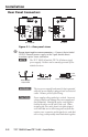
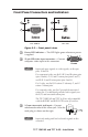
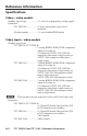
Rear Panel Connectors
AUDIO
AUDIO
12 VDC
.5A MAX.
OUTPUT
1 2 3 4 5 6 7 8
TP T 15HD 45
TP T A 45
AUDIO
AUDIO
12 VDC
.5A MAX.
3
1a
1b
2
TP T 15HD 45
TP T A 45
4
Figure 2-1 — Rear panel views
Ä
Power input captive screw connector — Connect the included
12 VDC external power supply to the 2-pole female direct
insertion captive screw connector.
N
The TP T 15HD 45 and the TP T A 45 share a single
power supply. Neither can be remotely powered by the
attached receiver.
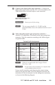
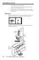
Power Wiring.eps
Power Supply
Output Cord
Captive Screw
Direct Insertion Connector
12 VDC
.5A MAX.
A A
SECTION A–A
+
+
W
The two power supply leads must be kept separated
while the power supply is plugged into an electrical
outlet. Remove power before wiring.
C
Power supply voltage polarity is critical. Incorrect
voltage polarity can damage the power supply and
the transmitter. Identify the power cord negative
lead by the ridges on the side of the cord. When
stripping the wire ends, please note that stripped
wire ends that are too short may pull out from the
captive screw connector and stripped wire ends that
are too long could possibly touch and short together.